The PT Boat Forum
http://www.ptboatforum.com/cgi-bin/MB2/netboard.cgi
ģ Forum Category: PT Boats of WWII
http://www.ptboatforum.com/cgi-bin/MB2/netboard.cgi?cid=101&fct=showf
ģ Forum Name: PT Boats - General
http://www.ptboatforum.com/cgi-bin/MB2/netboard.cgi?fct=gotoforum&cid=101&fid=102
ģ Topic:
Mk18 Torpedo Tube Details
http://www.ptboatforum.com/cgi-bin/MB2/netboardr.cgi?cid=101&fid=102&tid=5267
I've previously designed parts for modeling the Mk18 tube, but I'm going back to do a better job of it, in 1:1 scale. I'm focusing on the 77 footers, so the early Mk18 is what I'm doing.
Thanks to Dick, Al, and others, we have some important BuOrd drawings for the Mk18-Mod1 and -Mod5. But the existence of Mod1 suggests an earlier original Mk18, Mod-nothing. I'll call it Mod0, even though that wouldn't be shown on any drawings.
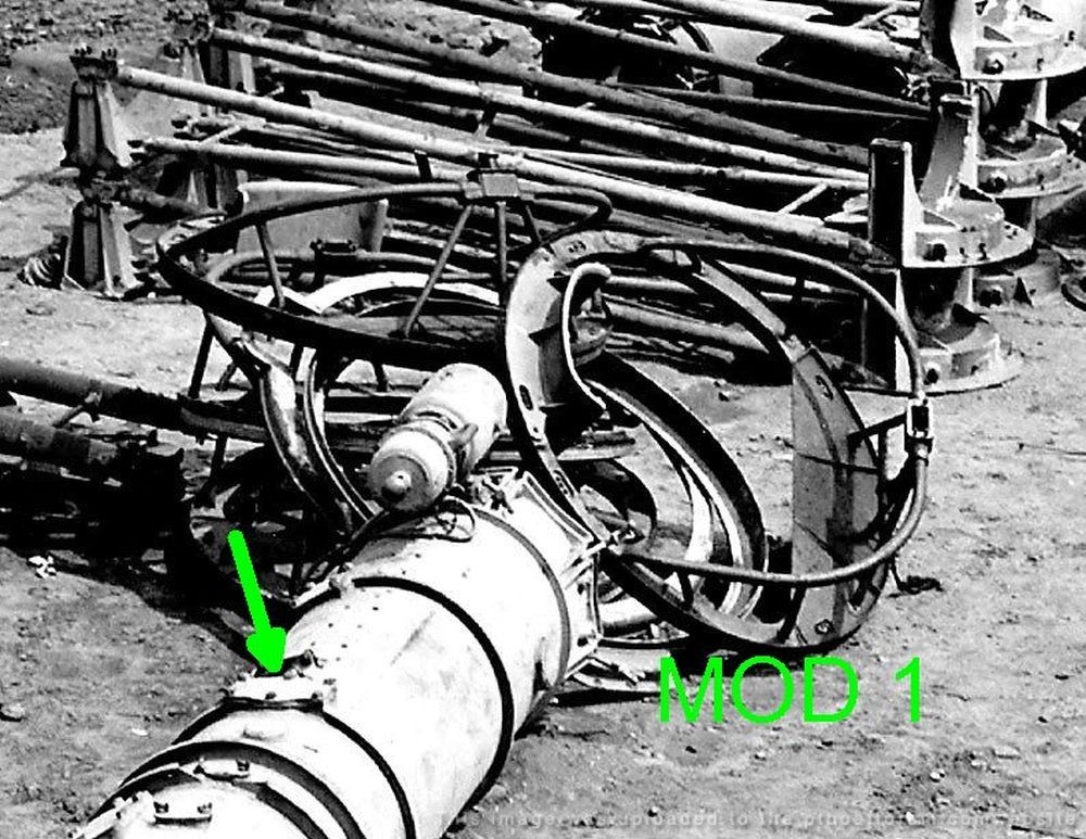
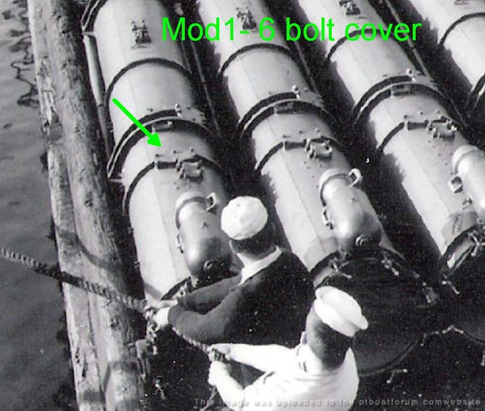
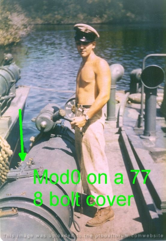
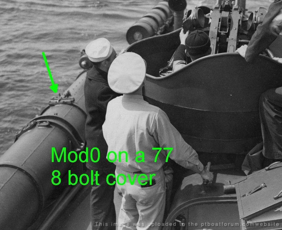
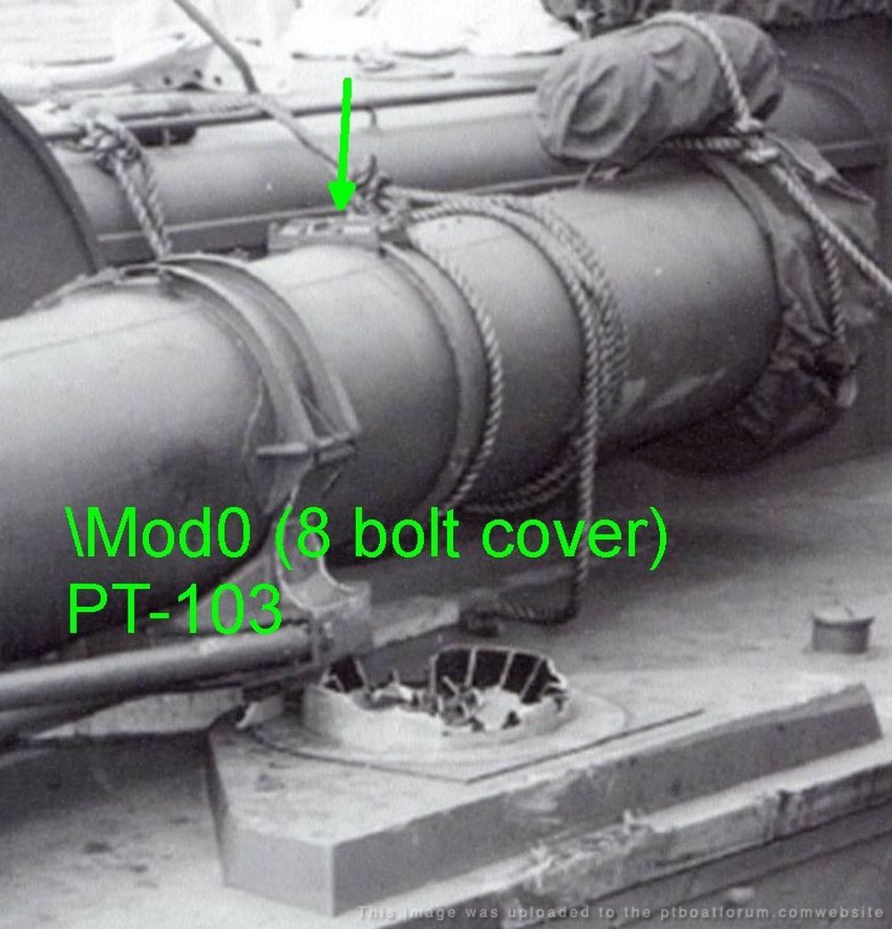
I believe that the 77s and early 103 class carried these Mod0's. As I plow through the drawings and photos while constructing my CAD model, I may spot more differences... But the first one I've found is an access plate (for what? I wonder)- just forward of the trip lever cover.
The Mod1 drawing shows it as a flat 6-bolt cover, and we see this in some photos. But photos of the early boats show a ribbed 8-bolt cover. With no drawings, I can only estimate its dimensions...probably very similar overall to the Mod1 6-bolt cover.
Anyone have more info on all this?
Images below show some of my work in-process, and clips from well known images that show Mod1 and Mod0

Posted By: Pat Matthews | Posted on: Sep 20, 2023 - 11:24am
Total Posts: 89 | Joined: Jan 7, 2012 - 5:41pm
BTW- that forward mount has a shaft through it and some links. More on that later! But I now think it had to do with thermal expansion...
Sure would be nice to find a clear image of the forward mount drawing. Al shared an image with me years ago, but it's a bit fuzzy.
I know I would have missed it since I visit too infrequently- but do we have good collection of Mk18 drawings yet? Did the drawings we have come from someone's collection, or directly from NARA? I have no idea where at NARA these would be...
Posted By: Pat Matthews | Posted on: Sep 20, 2023 - 11:30am
Total Posts: 89 | Joined: Jan 7, 2012 - 5:41pm
Hi Pat,
I think this cover was to provide access to the torpedo depth setting or gyro setting socket. They were not normally used by the PT Boaters unless they needed to change those settings after loading the torpedo into the tube. The specific one you point out is most likely for the gyro.
Jerry
Jerry Gilmartin
PT658 Crewman
Portland OR
Posted By: Jerry Gilmartin | Posted on: Sep 20, 2023 - 2:53pm
Total Posts: 1484 | Joined: Oct 8, 2006 - 11:16pm
Thanks Jerry.
Mod numbers: As long as I'm making up Mod numbers, how about Mod 1.5?
BuOrd dwg 294116 shows the tube drilled to accept rivets to attach the cast aluminum breech ring, 294107.
The later tube assy dwg 318384 shows welded-on steel parts to accept the breech door toggle bolts.
Both drawings are labeled Mk18 Mod1. This was a significant design change, but apparently not significant enough to drive a Mod number bump.
My old 3d-printable breech ring, based on 294107:
Posted By: Pat Matthews | Posted on: Sep 20, 2023 - 4:39pm
Total Posts: 89 | Joined: Jan 7, 2012 - 5:41pm
And why be concerned with these differences?
Any accurate model of an as-built 77 or early 103 class (to an unknown point) needs to have the right tube- the Mk18-"Mod.0". The differences are minor but they show even in smaller scales.
Posted By: Pat Matthews | Posted on: Sep 20, 2023 - 5:44pm
Total Posts: 89 | Joined: Jan 7, 2012 - 5:41pm
Another mystery: How was the tube attached to the rear mount (turntable)? For Mod.0/Mod.1.
The available drawings give no clue- the tube's flanges are shown without drilled holes or weld-studs. But the forward flange had to be drilled, as several photos show bolts through it.
Still, we have one clear photo of a 77's after mount, no bolts! Yet the cast aluminum turntable has milled slots to accept bolts or studs. Something is missing here,
Turntable with slots for bolts:
Forward mount with through-bolts:
Aft mount on a 77, with no visible means of attachment:
Drawings show nothing on the after flange. Same on the fwd flange, which we know IS drilled for bolts:
Posted By: Pat Matthews | Posted on: Sep 21, 2023 - 10:17am
Total Posts: 89 | Joined: Jan 7, 2012 - 5:41pm
A possible answer to this rear mount question:
Al shared an almost- final assy drawing for the Mod.1 (I think) tube... it hints at nuts UNDER the flange, which infers weld studs on the tube's after flanges.
Aft mount... drawing seems to show nuts and studs under the flange. Wish we had clear copy of this!
Posted By: Pat Matthews | Posted on: Sep 21, 2023 - 10:33am
Total Posts: 89 | Joined: Jan 7, 2012 - 5:41pm
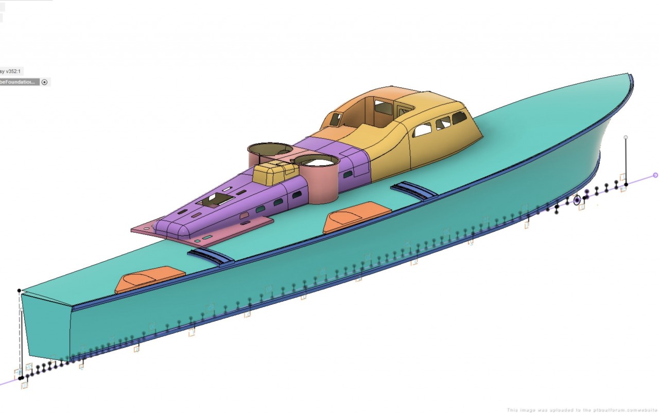
The Mk18 Mod.1 CAD model is mostly done, just missing a few fasteners hare and there. Next I'll go back and make changes to roll the design back to Mk18 Mod.0, as used on the 77s and early 80s. Oh, and the training gear, have to add the training gear.
There are a number of discrepancies, mainly due to not having good copy, or any copy, of several drawings. In several places, the details are speculative, but still based on photos and reasonable extrapolation of hints found in the extant drawings.
Another task: While the 3D CAD model is useful to some, 2D annotated drawings are needed too. That's coming.
Starboard forward tube shown:

Posted By: Pat Matthews | Posted on: Sep 23, 2023 - 4:22pm
Total Posts: 89 | Joined: Jan 7, 2012 - 5:41pm
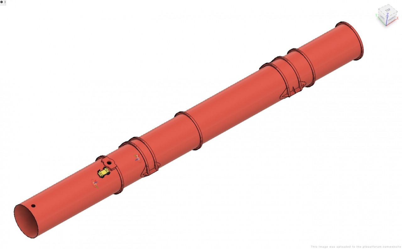
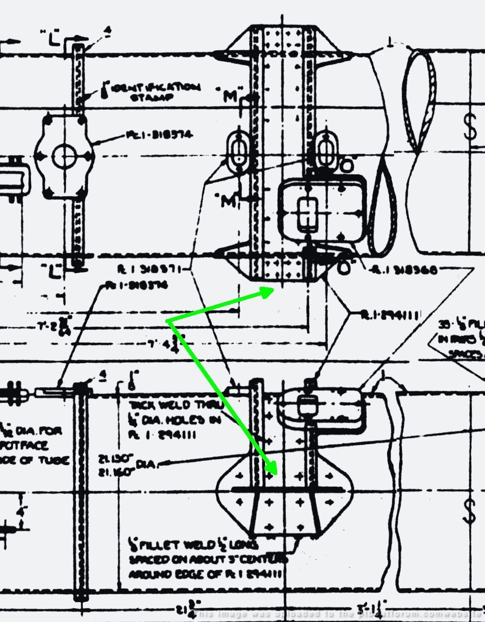
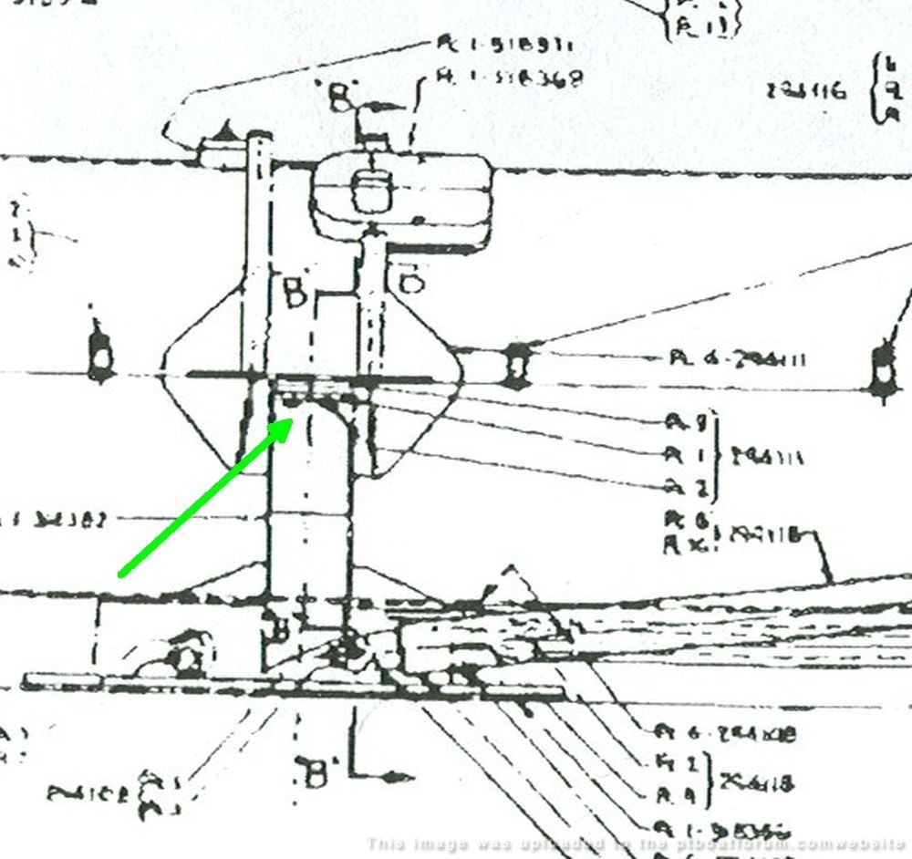
And what about that forward mount?
Ever since I first started working on designs for models of the 77s in 2004, it's been a goal of mine to figure out what was going on with that thing. Mysterious, as there is clearly a shaft that runs transversely through the mount with links on either side.
I think I finally got it.
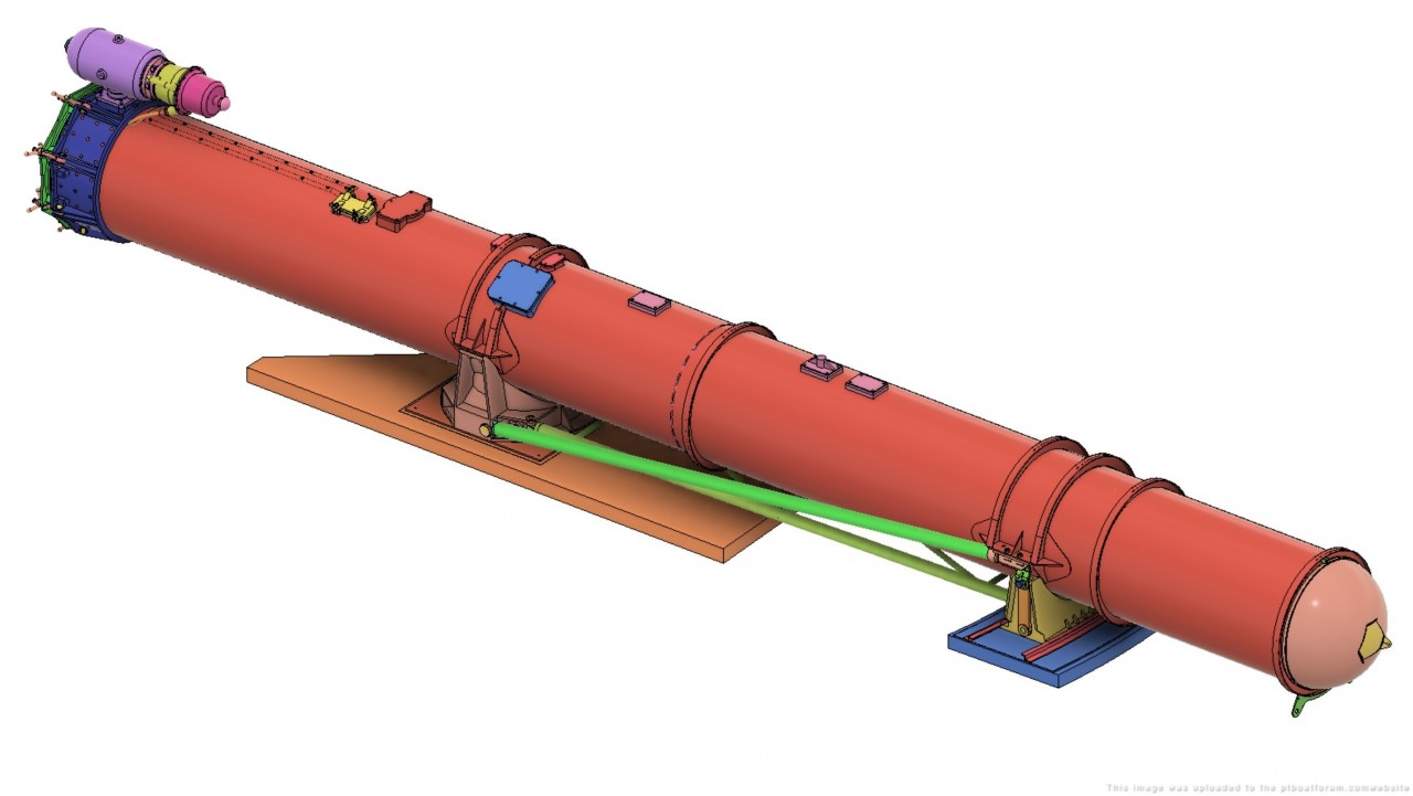
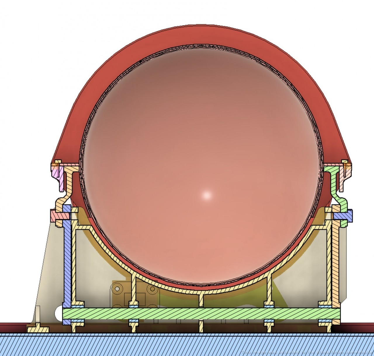
First, it's clear to me that the designers were worried about keeping the trainable tube straight on the deck of a wood boat...that's why we have what may have been overkill in trusswork and other details in the assembly. Â
The tube has cast aluminum supports, at the turntable and the forward sliding mount. The tube does not rest directly in the mounts' saddles, but its flanges sit atop the mounts. The tube is rigidly bolted to the the rear mount (turntable), but sits on a pivoting mechanism on the forward mount. Â
This pivoting mechanism must have allowed for thermal expansion and contraction of the tube relative to the wood deck it was mounted on. This could be ¹1/16" over the 9 foot mount separation, from 0 to 120°F. Not much, but enough to bend the tube or loosen the mounts at the deck.
(Boy, I sure we we had the rest of the detail drawings!)
This image shows the trusswork and struts connecting the two mounts and preventing racking in 2 planes.Â
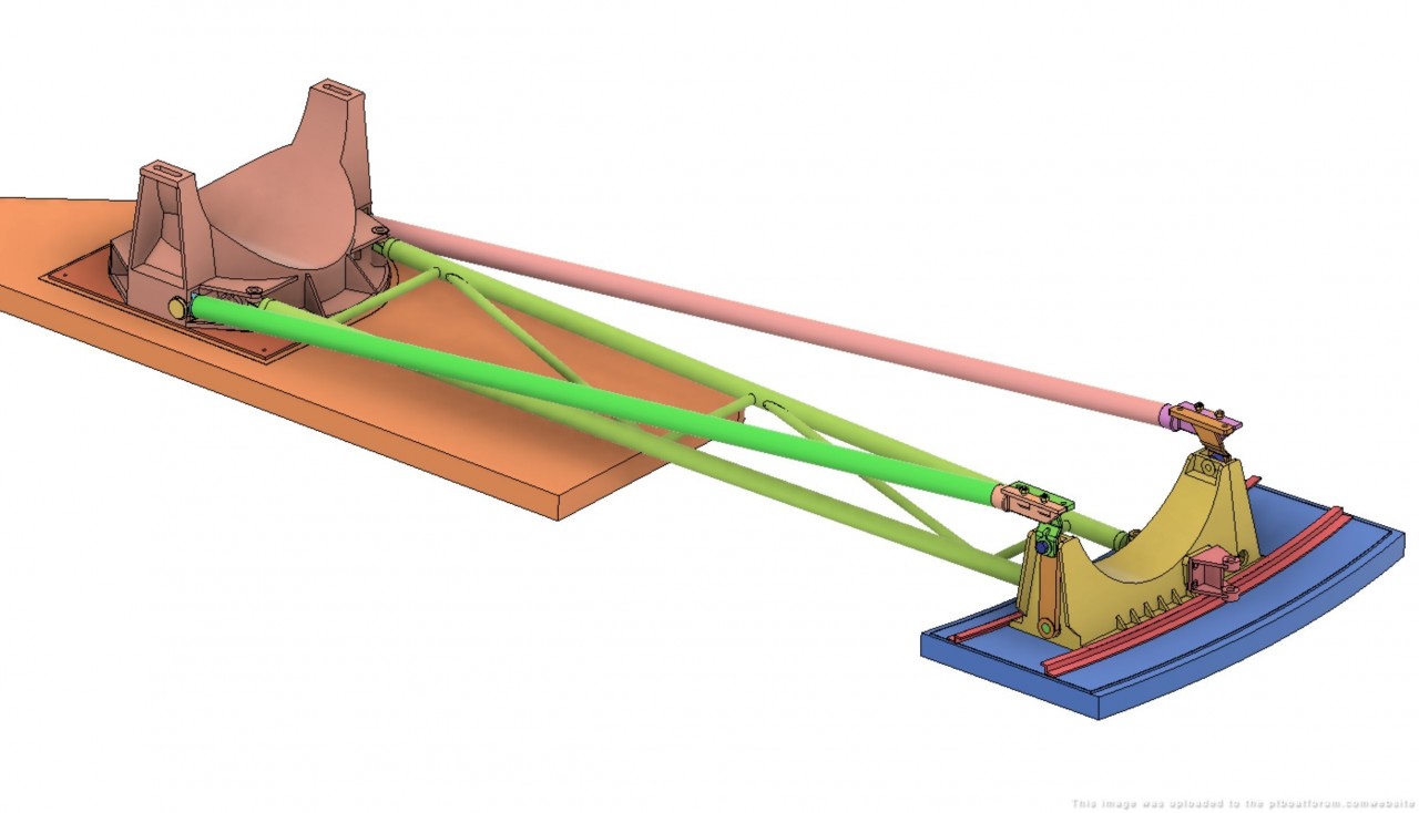
In this image:
A is the diagonal side strut and its end fitting, rigidly bolted to the forward tube flange.
B is a bracket also bolted to the tube flange, and pinned to the rotating link below it. The link itself pivots on a shaft in bearings running through the mount.
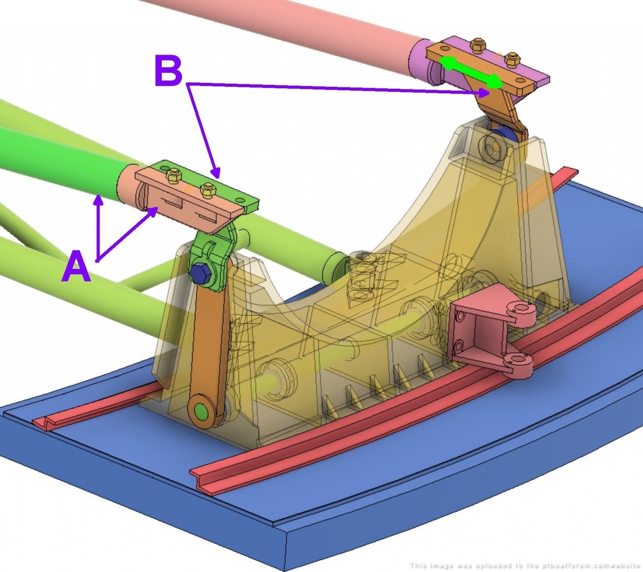
This section also shows the shaft and links.
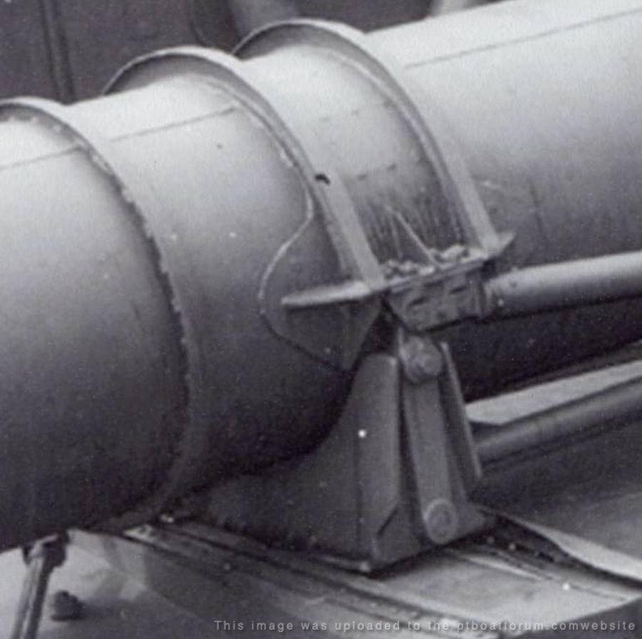
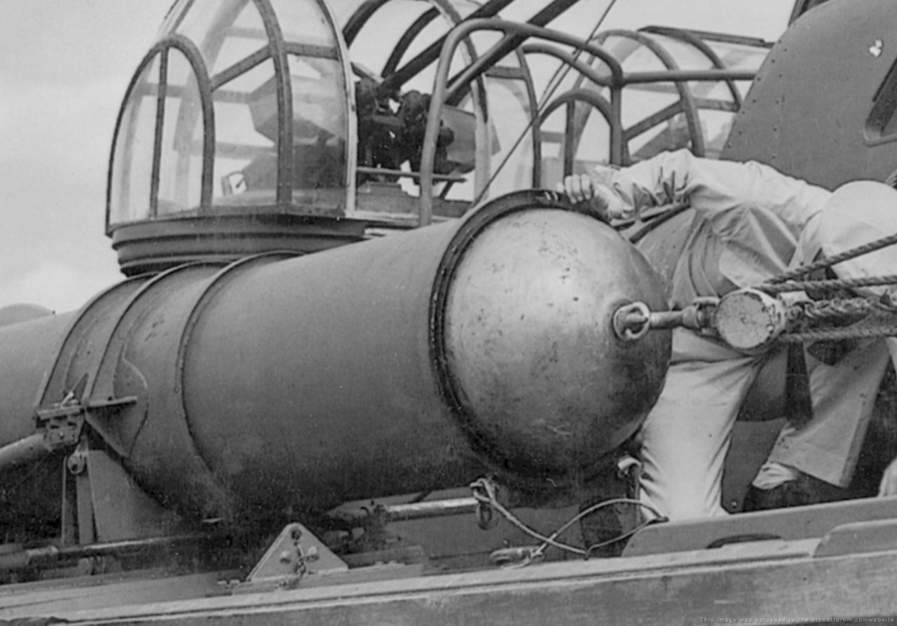
Finally, these two clips from the photos are the best views we have of this forward mount arrangement.

Posted By: Pat Matthews | Posted on: Sep 23, 2023 - 4:57pm
Total Posts: 89 | Joined: Jan 7, 2012 - 5:41pm
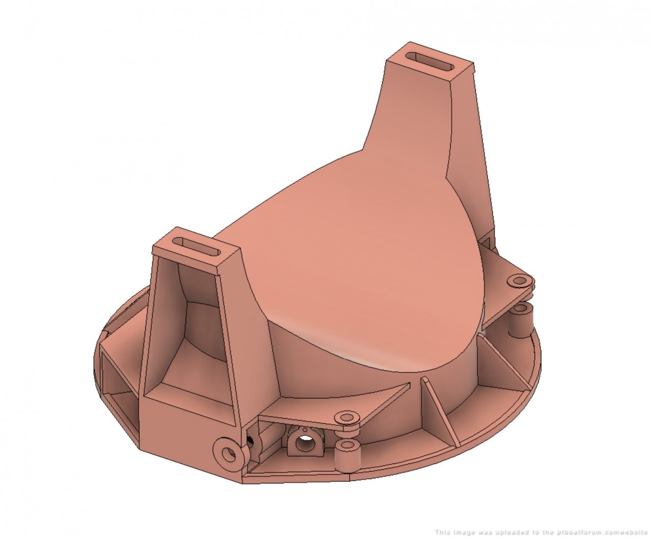
Here's another detail- the combustion chamber, key to launching the fish out of the tube.
We have drawings for most of it, but not for the charge itself nor the firing mechanism and its cover, which I have drawn as well as possible.
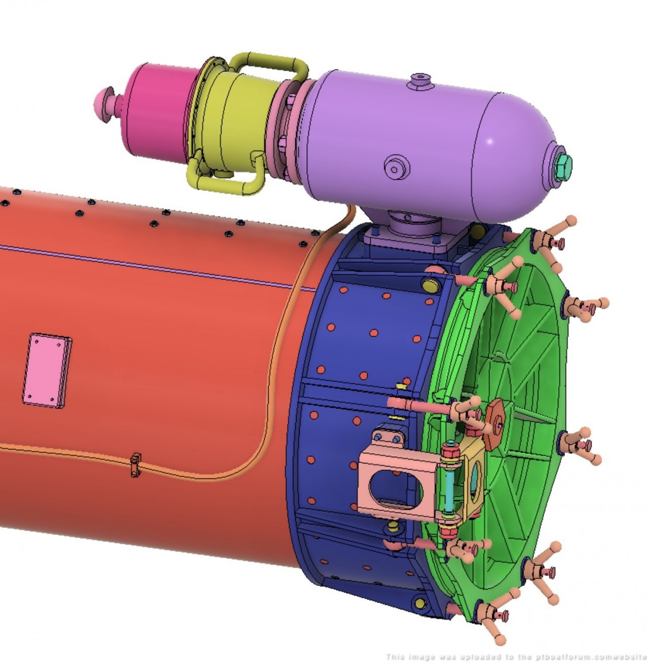
The main chamber is bolted to the tube, while the charge holder and firing mechanism are designed for quick change-out with a stagger-cut Acme thread.
The primary method for firing the charge is electrical. Not a hot wire, as with a model rocket engine! But I believe there was a solenoid inside the cover that drove a firing pin. And of course you could whack the pin with a mallet if need be.
Solenoid would be to the right, while the charge would be loaded in the pink adapter in the middle.
Posted By: Pat Matthews | Posted on: Sep 23, 2023 - 5:14pm
Total Posts: 89 | Joined: Jan 7, 2012 - 5:41pm
It's done! Here's the text from my FB post about it:
Torpedo Tubes for ELCO PT BOATS
The Mk.18 torpedo tube, which launched the Mk.8 21â torpedo, was used on Elco PT boats beginning with the 77 footer and part way into the production of the 80 foot PT-103 class in its original form that I call Mod.0. Mods 1 through 5 followed, but you need a Mod.0 on your 77 footer or PT-109 80 footer. And it does differ in some visible ways from Mod.1, but it's not a well documented design.
I've been frustrated by the incomplete details needed to accurately model this very visible part of the early Elco PTs. A number of modeler's drawings exist, but they don't shed light on all the mysteries of this complicated assembly.
So I've assembled all the available Electric Boat drawings and the handful of historic photos that show any detail of the tubes, and built a complete CAD model of the tube in 1:1 scale. This project allowed me to fill in many of the blanks, interpolating between the existing knowns to flesh out possible solutions for the unknowns.
The 3D CAD model, my 2D drawings, and historic reference material is now all posted at GrabCAD:
[url]https://grabcad.com/patrick.matthews-1/[/url]
GrabCAD is a trusted file sharing site run by the 3D printing technology giant Stratasys. Downloads are FREE but you do need to sign in there. Note that my model is NOT directly usable for 3D printing! But a CAD designer can work up printable parts from this information.
Once there, PLEASE read the NOTES document which provides much more additional detail on the torpedo tube and the available files.
CREDIT: All the source information comes from the PT boat community, in Groups like this, at the PT Boat Forum, and from books by more PT boat fans. Thanks to all who keep contributing to the knowledge base!
Screen cap from the GrabCAD site:
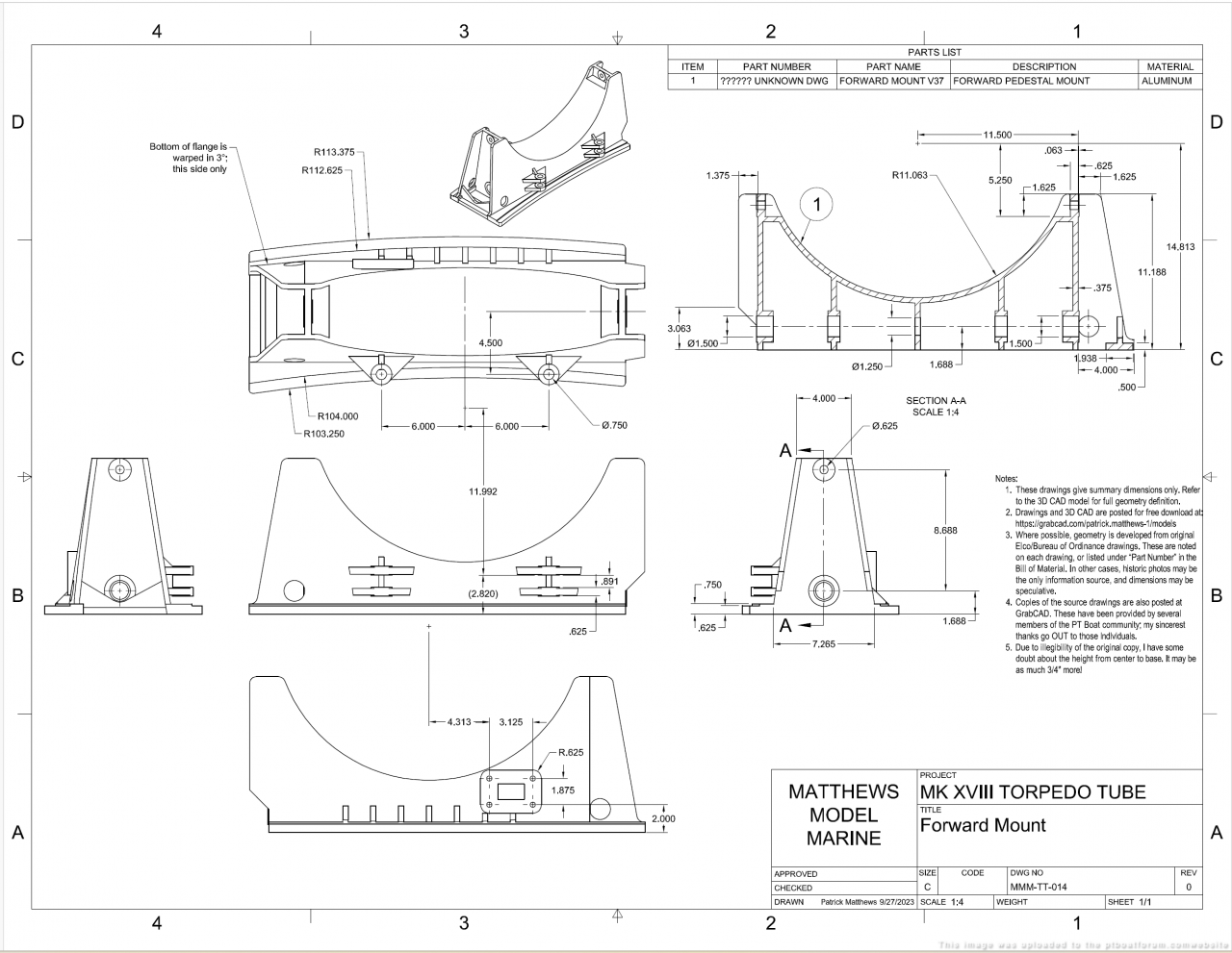
My top level assembly drawing:
One of 20 detail drawings:
Posted By: Pat Matthews | Posted on: Oct 1, 2023 - 8:59pm
Total Posts: 89 | Joined: Jan 7, 2012 - 5:41pm
Pat, outstanding work as usual!
Posted By: frankd | Posted on: Oct 2, 2023 - 11:02am
Total Posts: | Joined: Unregistered
A detail I hadn't noticed before:
The earliest tubes have the portable front cover retained by three spring-loaded catch hooks. I can just imagine these popping loose when the boat pounds on a few waves.
This design was replaced with a tensioned cable set up to a small triangular bra that held the dome in place. A lower cable was strung through the bra and attached by shackles to either side of the tube stop. The upper cable had some sort of tension adjuster and hooked to the top of the tube.
But here's a first-series 77, still has the turret domes in place, and it has the newer cable set-up flopped onto the deck. So I have no idea when the change was made.
Posted By: Pat Matthews | Posted on: Oct 2, 2023 - 12:05pm
Total Posts: 89 | Joined: Jan 7, 2012 - 5:41pm
Pat - [b]Just outstanding . . . .[/b]
I knnow just how hard it is to pin something down on PT boat matters! The discrepancies between drawings and photo are specially frustrating. Even when you're lucky and can find a clear/sharp drawing of an item you might be working on, there is always the diassapointment when you can't confirm it on photos.
Your CAD work is outstanding and your patience dealing with all the incomplete and at time confussing data, is absolutetly commendable. As you know, you, Jeff, Al and myself have been dealing with these issues for many-a-year.
Thanks for posting all your work here on the forum it is very much appreciated. The popularity of Facebook has drained many visitor from the forum over the last few years. Currently with only 30 or so visitors a day is a far difference from the 400 to 300 visits we use to get regularly. However, we can always count of the old Senior members, to visit atleast a couple times a week (thanks gang).
Keep up the excellent work! ! ! ! and please keep posting all your work here at the forum. To. see your great work always puts a smile on my face and I'm sure others also.
Dick . . .
Posted By: Dick | Posted on: Oct 11, 2023 - 1:24pm
Total Posts: 1486 | Joined: Aug 27, 2006 - 6:36pm
Pat - [b]Just outstanding . . . .[/b]
I knnow just how hard it is to pin something down on PT boat matters! The discrepancies between drawings and photo are specially frustrating. Even when you're lucky and can find a clear/sharp drawing of an item you might be working on, there is always the diassapointment when you can't confirm it on photos.
Your CAD work is outstanding and your patience dealing with all the incomplete and at time confussing data, is absolutetly commendable. As you know, you, Jeff, Al and myself have been dealing with these issues for many-a-year.
Thanks for posting all your work here on the forum it is very much appreciated. The popularity of Facebook has drained many visitor from the forum over the last few years. Currently with only 30 or so visitors a day is a far difference from the 400 to 300 visits we use to get regularly. However, we can always count of the old Senior members, to visit atleast a couple times a week (thanks gang).
Keep up the excellent work! ! ! ! and please keep posting all your work here at the forum. To. see your great work always puts a smile on my face and I'm sure others also.
Dick . . .
Posted By: Dick | Posted on: Oct 11, 2023 - 1:26pm
Total Posts: 1486 | Joined: Aug 27, 2006 - 6:36pm