The PT Boat Forum
http://www.ptboatforum.com/cgi-bin/MB2/netboard.cgi
ģ Forum Category: PT Boats of WWII
http://www.ptboatforum.com/cgi-bin/MB2/netboard.cgi?cid=101&fct=showf
ģ Forum Name: PT Boats - General
http://www.ptboatforum.com/cgi-bin/MB2/netboard.cgi?fct=gotoforum&cid=101&fid=102
ģ Topic:
Radio Antenna Question
http://www.ptboatforum.com/cgi-bin/MB2/netboardr.cgi?cid=101&fid=102&tid=4976
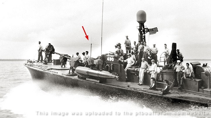
Is this a UHF antenna?
Posted By: pbudzik | Posted on: Jan 25, 2021 - 9:58pm
Total Posts: 17 | Joined: Apr 20, 2020 - 11:02am
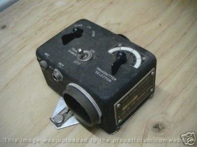
No this is a VHF dipole antenna with a ground plane for the RT19/ARC4 Radio used to talk between PT Boat and Aircraft. We obtained and mounted an ARC4 and then we had to have a duplicate antenna made to mount on board PT658 back in April 2017.
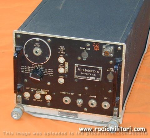
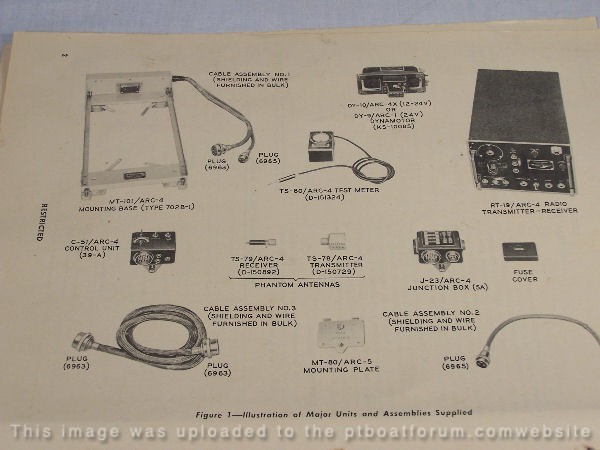
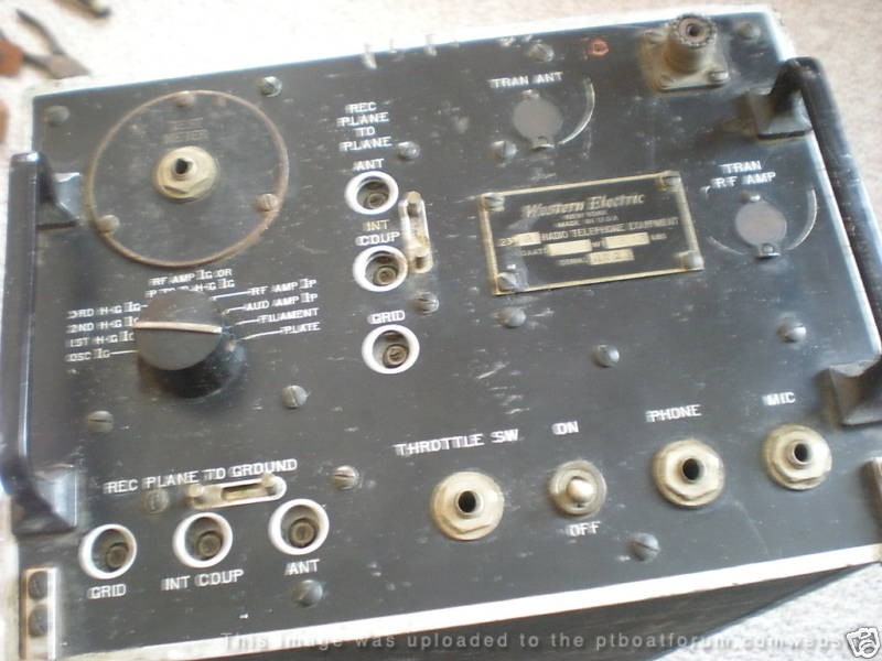
Here are the particulars on the ARC4
AN/ARC-4 RT-19
WE-233 âWestern Electricâ
Airborne VHF Receiver-Transmitter
Year 1943
The Receiver-Transmitter AN/ARC-4 RT-19 WE-233 equipment is a VHF communication unit designed for aircraft use in the 140 to 144 Megacycles band. It is intended for two way radio-telephone communication between airplanes and from airplanes to ground stations. It also provides an interphone system for the pilots.The equipment consist of a VHF transmitter and a VHF receiver mounted on a single chassie. Both the transmitter and the receiver may be pre-tuned for operation on any four crystal controlled frequencies in the 140 to 144 Magacycles. One of the four frequencies is intended for plane-to-plane communication. The remaining frequencies are intended for plane-to-ground communication. A transmitter crystal and receiver crystal are mounted in a single crystal holder and are so selected that the transmitter and the receiver both operate on the same carrier frequency. Crystal switching relays incorporated in the equipment permit the rapid selection of any of the four pre-tuned carrier frequencies. The radio receiver has two independent r-f input circuits which permit simultaneous monitoring on two carrier frequencies. One input circuit may be used to monitor continuously on the plane-to-plane carrier freuency. The other input circuit may be used simultaneously to monitor any one of the plane-to-ground frequencies. Provision is made to temporarily disable either circuit if two signals are received at the same time.
Frequency coverage: 140 â 144 MHz crystal controlled
Signals : AM Rx
Tubes : 4 x 6SN7 , 2 x 6AC7 , 3 x 12SJ7 , 2 x 12SQ7 , 2 x 12A6 Tx Tubes : 2 x 6V6 , 2 x 1614 , 2 x 6L6 , 1 x 832
Antenna: a quarter-wave
Output Power: 5-10 watts
Emission: A3
Power supply: 12 or 24 Volts DC
Dimensions: 19 1/2 x 10 7/16 x 7 11/16 in
Weight: 33 pounds
Manual: AN-08-10-245
Jerry Gilmartin
PT658 Crewman
Portland OR
Posted By: Jerry Gilmartin | Posted on: Jan 26, 2021 - 1:37am
Total Posts: 1472 | Joined: Oct 8, 2006 - 11:16pm
Jerry ...Thank you for coming to the rescue again!
Posted By: pbudzik | Posted on: Jan 26, 2021 - 4:54am
Total Posts: 17 | Joined: Apr 20, 2020 - 11:02am