The PT Boat Forum
http://www.ptboatforum.com/cgi-bin/MB2/netboard.cgi
ģ Forum Category: PT Boats of WWII
http://www.ptboatforum.com/cgi-bin/MB2/netboard.cgi?cid=101&fct=showf
ģ Forum Name: PT Boats - General
http://www.ptboatforum.com/cgi-bin/MB2/netboard.cgi?fct=gotoforum&cid=101&fid=102
ģ Topic:
50 cal Mk 17 and 40 mm M3 mounts
http://www.ptboatforum.com/cgi-bin/MB2/netboardr.cgi?cid=101&fid=102&tid=4912
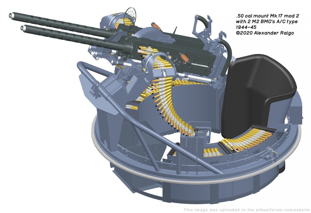
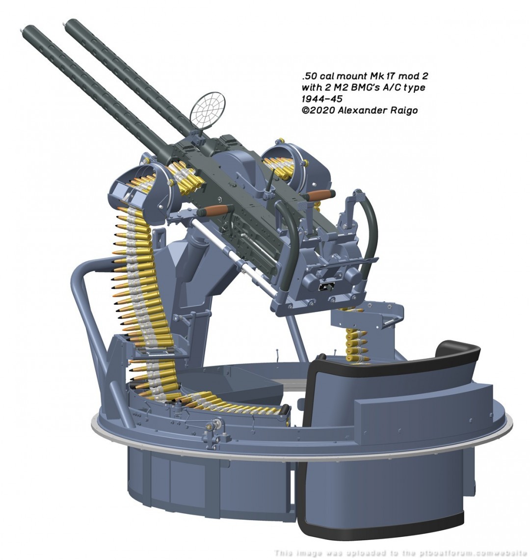
I am looking for detail information for these two very common mounts. I am producing CAD reconstructions of them that I need to mount in a variety of craft. I have already modelled the whole line of WW II .50 cal BMG's - this is a picture of my paired aircraft type ones, for example:
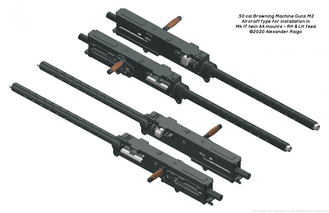
These are engineering models, by which I mean fully functional. The sources for information on the mounts are sparse in details (e.g. OP 951, OP 820, etc) and photos are few if any.
There were a number of them posted in this forum, but they are no longer available.
Can anyone help?
Than you in advance.
Posted By: modelwiz | Posted on: Feb 23, 2020 - 3:06pm
Total Posts: 8 | Joined: Feb 23, 2020 - 1:31pm
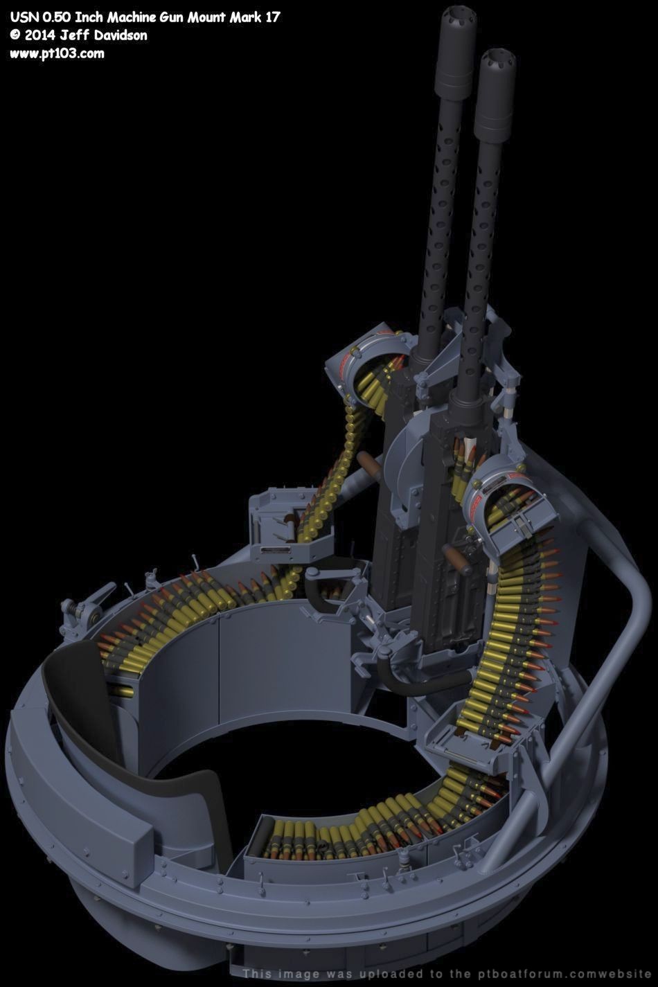
There's something about the rather plain boxy .50 cal. that I really like. If it's any help, I made a page for the Mark 17 mount to help modelers get it right. Jerry Gilmartin , a crewman aboard PT 658 out of Portland Oregon, helped a lot with measurements he took from the 658's mount. There's a drawing of it on this page: [url]http://www.pt103.com/PT_Boat_Components_Browning_50_Cal_M2_Twin_Mount_Mark_17.html[/url].
I've since learned that the load out of 1 tracer / 1 armor piercing I show is wrong. A manual typo showed it as such, it should be 1 tracer / 3-4 AP:
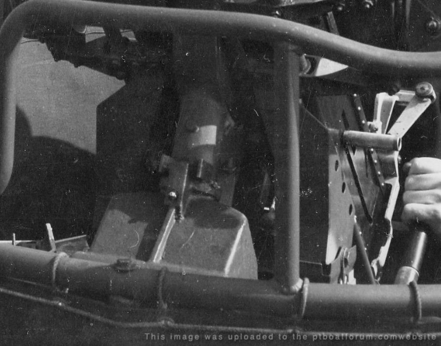
One part that I was never able to find good refs or photos of is the early carriage brake that operated against a ring around the base of the mount. You may have noticed in pictures the brake ring surrounding the lower part of the carriage. It was slightly less in diameter then the top of the turret:
Good luck with your project Alexander!
Posted By: Jeff D | Posted on: Feb 24, 2020 - 5:29am
Total Posts: 2200 | Joined: Dec 21, 2006 - 1:30am
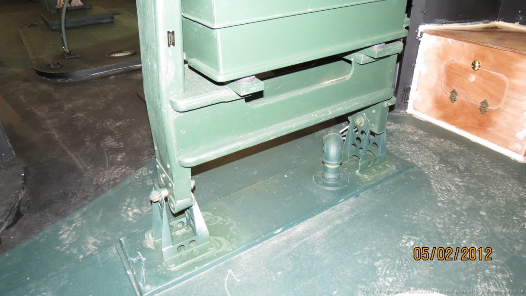
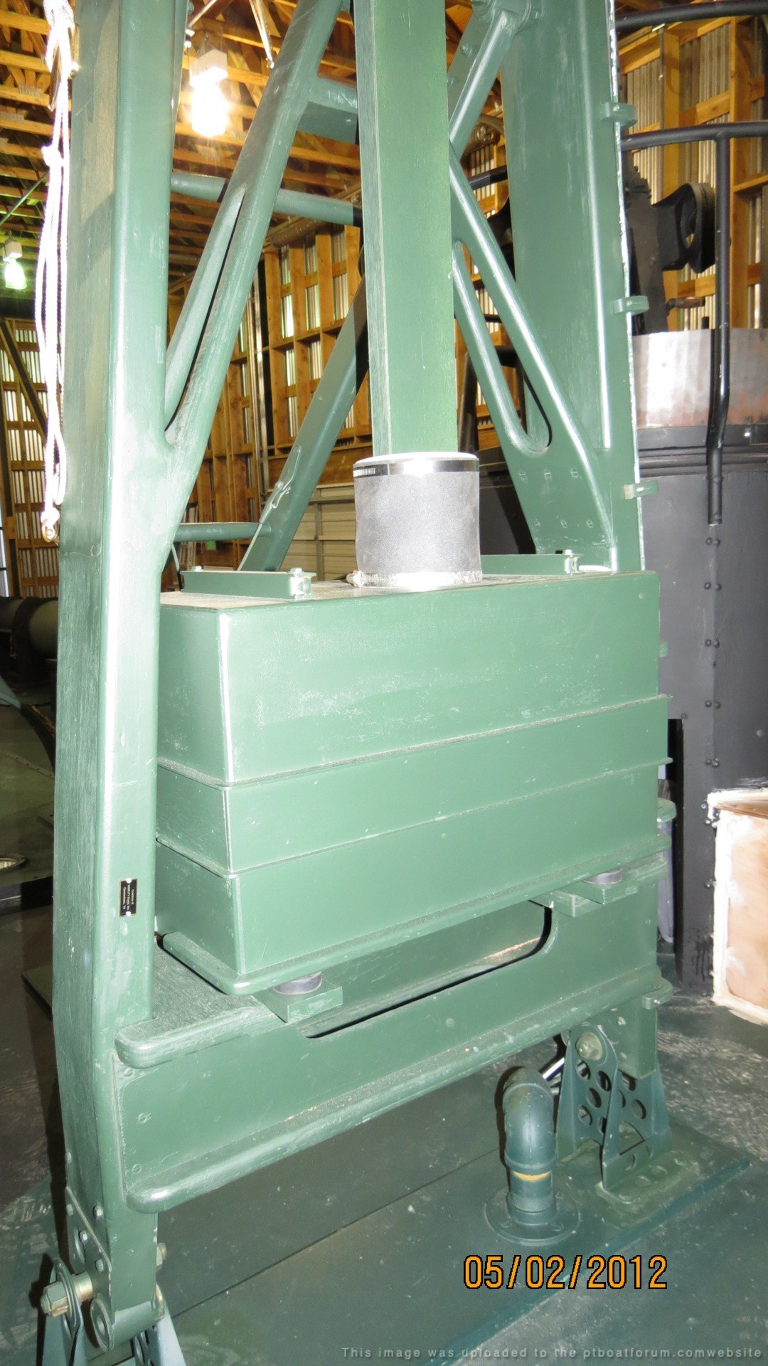
I forgot to mention another difference in the mount besides the brake ring, the support pedestal. A cast type was replaced by a welded type on the Mod 1 mounts. Vietnam era Mark 17 mounts show another change to the pedestal. Here's some images of the 2 types, I show the early type on my drawing:
The early cast pedestal:
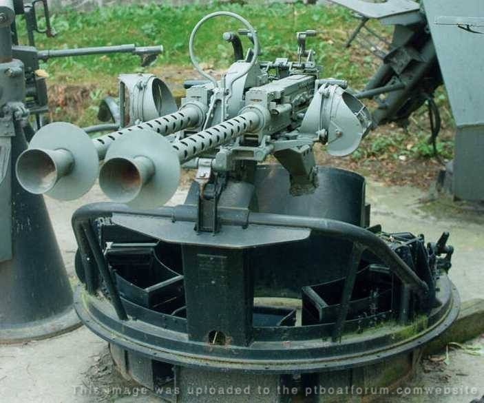
The later welded pedestal, shown here modeled by the handsome Jerry Gilmartin crewman aboard PT 658:
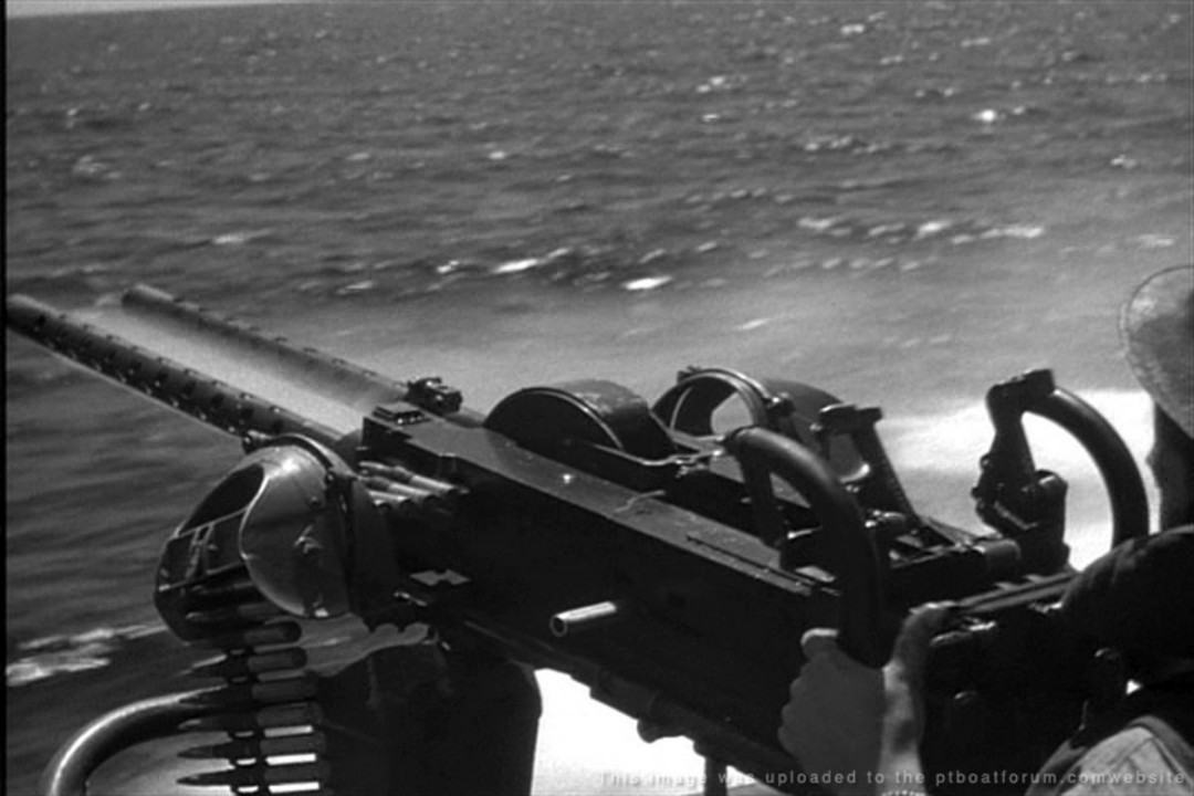
One part I noticed on the .50 that is different on modern guns is the mounting plate of the retracting slide. The front is longer.
Posted By: Jeff D | Posted on: Feb 24, 2020 - 10:00am
Total Posts: 2200 | Joined: Dec 21, 2006 - 1:30am
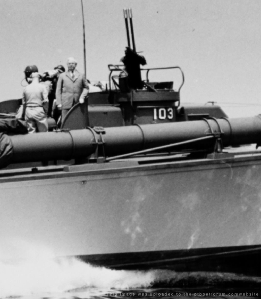
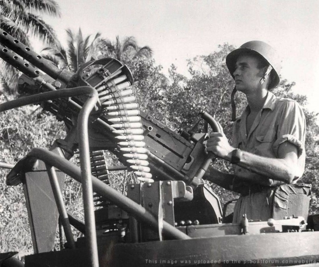
Also note that many and maybe most .50's had a straight bar charging handle. You can see it in the black and white photo.
David Waples
Posted By: David Waples | Posted on: Feb 24, 2020 - 9:30pm
Total Posts: 1679 | Joined: Jan 2, 2007 - 9:55pm
Yes, and although lighter and simpler it traveled back and forth with the bolt. You wouldn't want a hand to slip off a grip and into its path when firing!
They Were Expendable has a good non-studio scene showing the action:
Another scene shows some details of the underside of the mount from various angles:
Posted By: Jeff D | Posted on: Feb 25, 2020 - 4:32am
Total Posts: 2200 | Joined: Dec 21, 2006 - 1:30am
Thank you for your replies!!
The pedestal is one of the least clear elements of the mount - it appears to have been welded to the rail in a couple of cases, but not in others, and the manual mentions it as being bolted which does not seem likely given the layout.
And Jeff, your illustrations are mind-blowing at several levels. Whatever CAD program you are using allows you to produce such things as chains, ropes, guy wires, torsion springs and twisted ammo belts - Solidworks does that but each of them eat up gobs of memory I downloaded your six view rendering of the Mk 17 and when I scaled it up to 1:5 it became much sharper, which I have never seen before in a jpg. I did look carefully at your mast and regret it does not have an SO mounted on it -I only have the simplest of layouts for the antenna. Your renderings are impressive, too. Are your assemblies colored in Haze Grey? And yes, I freely admit I will be imitating most of your work in my Mk 17 - I need to.
Again, thank you.
After the 50's I will be tackling the 40 mm in single, twin and quad mounts but most details of the single mount upper carriage are quite obscure, hence my post. I will post renderings of my boat as soon as I can arm it
Posted By: modelwiz | Posted on: Feb 25, 2020 - 4:54am
Total Posts: 8 | Joined: Feb 23, 2020 - 1:31pm
Thank you for your kind words MW, they mean a lot to me especially since you know what a pain 3D can be. What really impresses me are the modelers that create the parts physically, no undo button for mistakes for them!
Did you grab the full size copy of the mount drawing? It is fairly large, 3800 x 2040. The image on the page is just a smaller preview.
I spent about a year full-time on the gun and mount including many hours of searching. I did the first version before the manual was available so had to go mostly by photos. Jerry Gilmartin was a great help there and also took measurements from the authentic carriage on PT 658. Most of the parts started as a box, cylinder, or tube. The belt was indeed a giant hairy PIA, placing each cartridge, moving and rotating, then repeating over and over until all was lined up. With my 6GB ram computer, I ended up having to render from a command line since the program would crash trying to do it the usual way. I sure was glad when it was finally done!
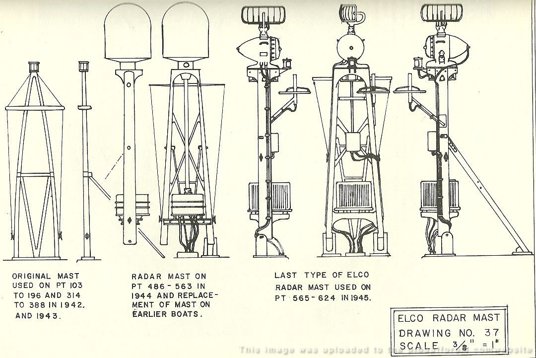
Here are some radar refs:
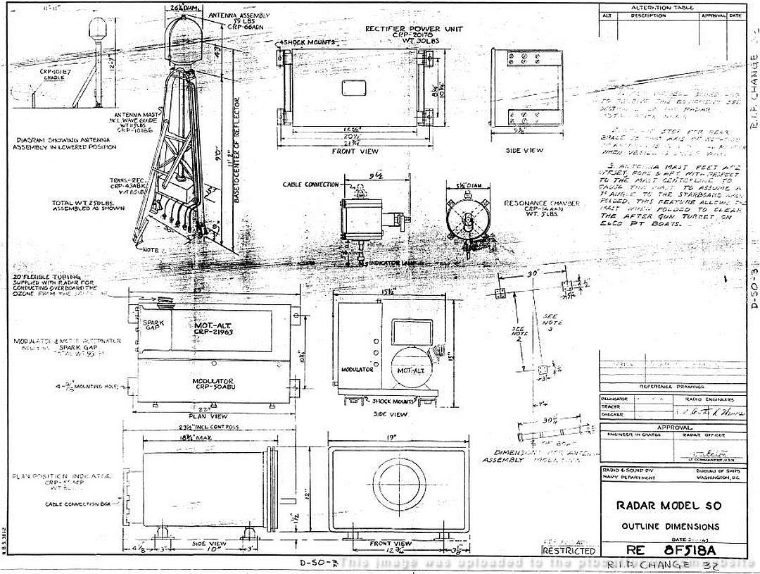
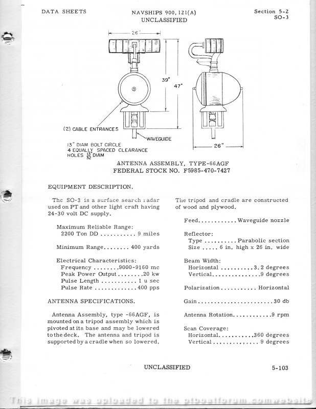
Does anyone know who to credit this drawing to?
Posted By: Jeff D | Posted on: Feb 26, 2020 - 7:02am
Total Posts: 2200 | Joined: Dec 21, 2006 - 1:30am
I meant to thank you for the drawings-that is more information on the masts than I ever found. I have a Higgins drawing for a PT mast that I downloaded in 9 different pieces and put together from the La library, but it is built completely different, with steel angles.
Are the main frame members in the SO mast wooden beams? They seem far lighter than hollow sheetmetal would be.
Thank you!!
Alexander
Posted By: modelwiz | Posted on: Mar 4, 2020 - 11:54pm
Total Posts: 8 | Joined: Feb 23, 2020 - 1:31pm
Alexander, the radar mast main beams are actually hollow. It seems like they were made from laminated wood about the size of a 2x8 on the outside, but obviously hollow interior for weight savings I imagine. I discovered this when we received our radar mast on loan from Don Shannon to mount on board PT658
Here are some pics of our radar mast
Authentic PT Boat Radar mast close ups on PT658

Jerry Gilmartin
PT658 Crewman
Portland OR
Posted By: Jerry Gilmartin | Posted on: Mar 6, 2020 - 2:46pm
Total Posts: 1473 | Joined: Oct 8, 2006 - 11:16pm
Great pics! Drawings, unless they are a complete manufacturing set, cannot cover all the construction details. These pics make the mast much clearer. Most of the equipment I have to deal with no longer exists, and documentation is seldom complete.
Thank you!
Posted By: modelwiz | Posted on: Mar 11, 2020 - 10:04am
Total Posts: 8 | Joined: Feb 23, 2020 - 1:31pm
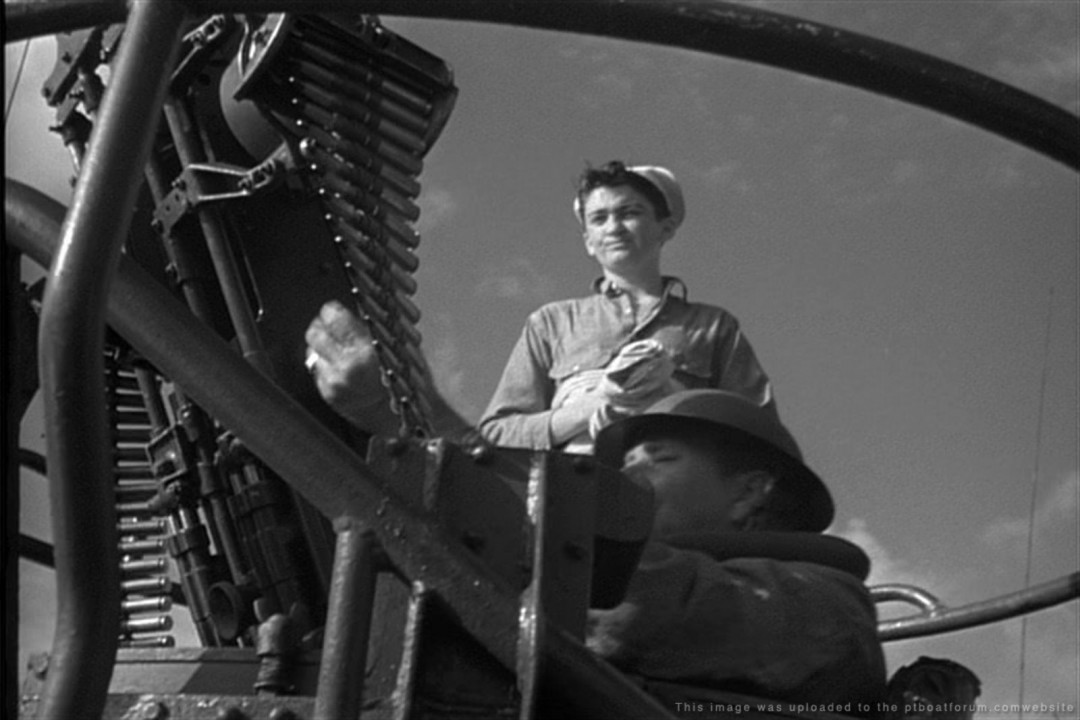
Here's shot of some shoe polishing, but in the background is a good shot of the base of a radar mast.
Charlie
Posted By: 29navy | Posted on: Mar 11, 2020 - 11:32am
Total Posts: 600 | Joined: Dec 28, 2006 - 3:02pm
Try again
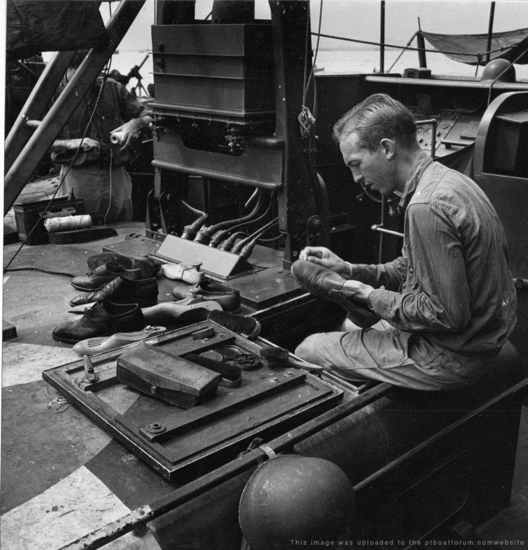
Charlie
Posted By: 29navy | Posted on: Mar 11, 2020 - 11:36am
Total Posts: 600 | Joined: Dec 28, 2006 - 3:02pm
That is one fine photograph, Charlie. Thank you.
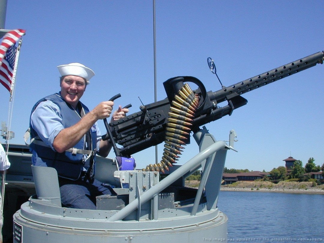
I have just finished my working model of a Mk 17 - ammo belts are particularly difficult to define in 3D CAD, and the ones in this mount are as complicated as they get. Other than that, I neede to apply the WAG method to a few things, but I am used to that. Jeff D's illustrations were instrumental in helping me to detail the mount. Thank you again for the info.
I will be tackling the radar mast fairly soon,
Any clear pictures of the SO antenna? I found a small one in an electronic equipment inventory manual, but other than the general shape and size of the radome, I've got nothing.
Here are a couple of views of the finished model of the mount (painted in haze grey, no less!)
Posted By: modelwiz | Posted on: Apr 12, 2020 - 6:08pm
Total Posts: 8 | Joined: Feb 23, 2020 - 1:31pm
Try again
http://ptboatforum.com/PhotoGallery/image/jekTs
http://ptboatforum.com/PhotoGallery/image/jeUcw
Posted By: modelwiz | Posted on: Apr 12, 2020 - 6:18pm
Total Posts: 8 | Joined: Feb 23, 2020 - 1:31pm
Try again
Posted By: modelwiz | Posted on: Apr 12, 2020 - 6:57pm
Total Posts: 8 | Joined: Feb 23, 2020 - 1:31pm
Not bad Alexander! Yes those ammo belts are a real pain. I'm glad to see you got the tracer / AP mix right, a typo in an online manual led me astray. I keep forgetting to fix it.
Posted By: Jeff D | Posted on: Apr 13, 2020 - 3:47am
Total Posts: 2200 | Joined: Dec 21, 2006 - 1:30am