The PT Boat Forum
http://www.ptboatforum.com/cgi-bin/MB2/netboard.cgi
ģ Forum Category: PT Boats of WWII
http://www.ptboatforum.com/cgi-bin/MB2/netboard.cgi?cid=101&fct=showf
ģ Forum Name: PT Boats - General
http://www.ptboatforum.com/cgi-bin/MB2/netboard.cgi?fct=gotoforum&cid=101&fid=102
ģ Topic:
Revell New Tool PT-109 Instruction Sheet
http://www.ptboatforum.com/cgi-bin/MB2/netboardr.cgi?cid=101&fid=102&tid=4350
Well, here are the instructions. A very nice effort from Revell Germany. I'm interested to see the finished parts. Have a look.
https://www.revell.de/fileadmin/import/images/bau/05147_%23BAU_PATROL_TORPEDO_BOATPT109.PDF
David Waples
Posted By: David Waples | Posted on: Feb 11, 2018 - 5:45am
Total Posts: 1679 | Joined: Jan 2, 2007 - 9:55pm
I'm happy to see the (3 piece) hull has a nice sheer line and water / exhaust outlets! And the deck has a decent camber. One too many starboard deck / dead lights but that's minor. The torpedo tubes look nicely detailed for the most part. An early mast is included.
Clickable link: [url]https://www.revell.de/fileadmin/import/images/bau/05147_%23BAU_PATROL_TORPEDO_BOATPT109.PDF[/url]
Builders should leave off part 91, looks like an aldis locker door for later boats maybe. The starboard bridge bulkhead was bare framing except for the door:
[image]http://www.pt103.com/images/PT_Boat_Elco_103_Class_Bridge_And_Chart_House_Perspective_Details_Stbd_Bridge.jpg[/image]
Also leave off the strange decal on the torpedo fire control box that Dave pointed out. :D
Posted By: Jeff D | Posted on: Feb 11, 2018 - 6:21am
Total Posts: 2200 | Joined: Dec 21, 2006 - 1:30am
Dave;
Looks great, but I think waterline would have been a better way to go, more functional for the modeler. You might want to pass that to Massimo for the 1/35 Higgins.
Take care,
TED
Posted By: TED WALTHER | Posted on: Feb 11, 2018 - 9:18am
Total Posts: 3059 | Joined: Oct 16, 2006 - 7:42am
I overlaid the Elco deck arrangement drawing over the deck shown in the instructions and all the houses, torpedo tube bases, turret locations, and other part locations visible on the deck matched up very very well. As long as the part drawing is an accurate depiction of the actual part, my picky butt is impressed! Besides the extra dead / deck light the only error I spotted is a missing cover on the throttle push rod deck housing just shy of the aft end of the day cabin. Again easy to fix. They did the cover very nice though, they even included the 2 different heights.
Posted By: Jeff D | Posted on: Feb 11, 2018 - 9:33am
Total Posts: 2200 | Joined: Dec 21, 2006 - 1:30am
They clearly did their homework. I'm not sure if they were working with anyone but I would say they spent some time looking at your 103 site Jeff and listening to my rants about the mast. Big tip off are the throttle line covers. That came straight from your site Jeff. I'm very glad they did include the A frame mast.
I thought the engine hatch was interesting. It was clearly designed to come off. It's like they thought they were going to add an engine room but then decided not to. There's room for some aftermarket upgrades. Steve's (a.k.a. model monkey) torpedo tubes would look great on this boat.
I suspect they left themselves some room to do some other boats with different features. I'm not sure why they have the plating on the bow section which you see in later Elco's. The way they designed the stern section was also curious.
Anyway, I think they put together a winner.
Dave
David Waples
Posted By: David Waples | Posted on: Feb 11, 2018 - 10:29am
Total Posts: 1679 | Joined: Jan 2, 2007 - 9:55pm
Yah I can see some details most likely garnered from my work with Dick's DVD. And Dick's work too, most likely we have him to thank for the neat hull outlets.
I think you are right about future releases, the deck insert for the 20mm could be another sign. Too bad there's no engine room details but I can understand why not. Sooo much detail in there to do it right.
One thing that looks off to me are the depth charges, I think they were farther aft and more inboard. This shot of what is supposed to be the 109 seems to show that:
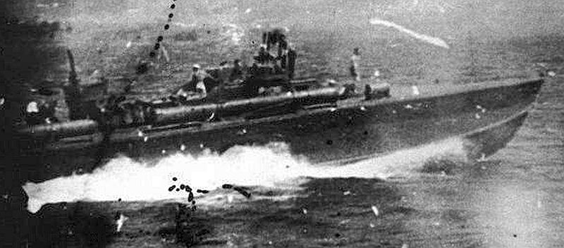
The molding for the depth charges is interesting. I wonder why they did it that way.
Posted By: Jeff D | Posted on: Feb 11, 2018 - 12:24pm
Total Posts: 2200 | Joined: Dec 21, 2006 - 1:30am
Yes, the depth charges were definitely more inboard. I wonder if it was the result of torpedoes sliding out of their tubes and pushing them through the deck as happened with Kennedy. The 109 wasn't the only boat built that way. Interesting how they designed the depth charge rack to straddle the toe rail.
Another place I saw your handy work is the armor plate behind the cockpit. I noticed that they included the hardware detail. Another nice detail are what you pointed out which were the vents on the side of the hull.
Dave
David Waples
Posted By: David Waples | Posted on: Feb 11, 2018 - 3:56pm
Total Posts: 1679 | Joined: Jan 2, 2007 - 9:55pm
Jeff and Dave;
Your right, being further back and close to the gunwhale is probably how the torpedo hit the depth charge.
In the photo you supplied, it looks to be about 3-3 1/2 feet from the gunwhale. If you look at photos of 77' Elcos there are additional rails added.
PT 38 RON 3(2) Tulagi 1943.
First series 77' ELCO escorting USS Nicholas(DD-449) into Tulagi Harbor, July 1943.
take care,
TED
Posted By: TED WALTHER | Posted on: Feb 11, 2018 - 4:32pm
Total Posts: 3059 | Joined: Oct 16, 2006 - 7:42am
Hello,
Just a nitpick,
Looks like the starbd. forward window on the daycabin is the same as the rest but should be a deadlight. Also the dayroom hatch opened to port on the early boats but this could have been modified in the field to open aft. At least they got the stagger on the daycabin correct. Maybe remove the torpedo cranks, but these could also have been retrofitted. Some decent footrails would improve it greatly. Not a bad effort though and a good basis for detailing. IMHO [:-smilearound-:]
Best Regards,
Stu.
Posted By: Stuart Hurley | Posted on: Feb 12, 2018 - 4:37am
Total Posts: 255 | Joined: Mar 19, 2013 - 3:32am
Yes Stu that day cabin dead light would have been a nice detail. The glass was at the surface as opposed to sunk in on the windows so would have added some interest. An easy way to show a difference would be to remove the drip rail above it.
A gentleman on Frank's Facebook page was asking about how the 37mm was mounted to the deck. This is interesting and although contrary to popular opinion it is said to be straight from the horse's mouth: [url]http://www.orwelltoday.com/jfkpt109.shtml[/url]
Here are some quotes from the article regarding source and the 37mm:
[green]The following story entitled SURVIVAL appeared in NEW YORKER magazine in early 1944. It was written by journalist John Hersey from notes taken while he visited John Fitzgerald Kennedy in the New England Baptist Hospital in Boston a few months after the events of August 1-2 1943. JFK was recuperating from malaria and surgery on his back. The disc between his fifth lumbar vertebra and his sacrum had ruptured during the crash in the Solomons. JFK agreed to the interview and asked Hersey to also talk with some of his crew. They filled in the gaps.
Kennedy whirled the wheel to the left, but again the 109 did not respond. Ross went through the gallant but futile motions of slamming a shell into the breach of the 37-millimetre anti-tank gun which had been temporarily mounted that very day, wheels and all, on the fordeck.
So they took an inventory of their armament. The 37-millimetre gun had flopped over the side and was hanging there by a chain.
Those who could not swim well grouped themselves around a long two-by-six timber with which carpenters had braced the 37-millimetre cannon on deck and which had been knocked overboard by the force of the collision.[/green]
If it were me I'd make sure the lashing would not only keep the 37mm from moving back it would also keep it from moving forward. The Revell kit shows lashings that seem to only keep it from moving back. I'd also have the 37mm on wheels and chained at key stress points, to the mooring bitt, maybe wrapped around the axle ends behind the wheels and led to the cleats (have to move the depth charges back) and foot rails in an X pattern, as well as roped down at the aft ends to keep it from twisting. I feel confident that this way is probably most likely totally partially wrong.
Posted By: Jeff D | Posted on: Feb 14, 2018 - 7:36am
Total Posts: 2200 | Joined: Dec 21, 2006 - 1:30am
I've been thinking a lot about my guess as to how they might have secured the 37mm and changed my mind / refined from what I had posted earlier.
Chained from the mooring bitt to the axle, then from the ends of the carriage trails (legs) to the cleats (have to move the depth charges back). The 2x6's from inside the wheels to the ends of the trails with the axle and trail ends lashed down to them to prevent the gun from lifting.
The Revell kit 37mm lacks carriage wheels, I plan on creating some for 3D printing for those that want them as well as scale foot rails.
Posted By: Jeff D | Posted on: Feb 14, 2018 - 6:36pm
Total Posts: 2200 | Joined: Dec 21, 2006 - 1:30am
Hello Jeff
I remember a while back the popular belief was that the wheels had been removed and brackets fabricated to secure the axle stubs to the planks.
Interesting to hear the mention of chain to help lash the gun down.
Best Regards,
Stu.
Posted By: Stuart Hurley | Posted on: Feb 15, 2018 - 4:35am
Total Posts: 255 | Joined: Mar 19, 2013 - 3:32am
Yes, and that the gun wasn't able to fire and that coconut logs were used. Although I don't believe everything I read in a newspaper this article has the advantage of being a relatively short time after the incident and taken from those that were there. And none of the details would make the article "sell" better so there's no reason to fabricate "fake news" about them.
Posted By: Jeff D | Posted on: Feb 15, 2018 - 6:17am
Total Posts: 2200 | Joined: Dec 21, 2006 - 1:30am
Pitch the 37mm. Who needs it! [:-cheers-:]
David Waples
Posted By: David Waples | Posted on: Feb 15, 2018 - 5:18pm
Total Posts: 1679 | Joined: Jan 2, 2007 - 9:55pm
Hello Jeff
I remember a while back the popular belief was that the wheels had been removed and brackets fabricated to secure the axle stubs to the planks.
Interesting to hear the mention of chain to help lash the gun down.
Best Regards,
Stu.
As much as I loathe discussing PT 109, that scenario comes from Donovan's PT 109 (page 97 in my edition)
(quote) When the Higgins boat came alongside, they hauled the anti-tank gun and a couple of two-by-eight planks aboard. They laid the two planks along either side of the foredeck. Then they lifted the gun, the wheels of which had been removed, and placed it in position with its axles resting on the planks. After that, they waited for some carpenters to come out from Lumberi to nail down the planks and bracket the axles to them.(end quote)
Donovan interviewed the survivors, so his information was coming from primary sources. The plot thickens...
[:-question-:]
Posted By: alross2 | Posted on: Feb 15, 2018 - 7:45pm
Total Posts: 993 | Joined: Oct 30, 2006 - 8:19pm
Hello Jeff
I remember a while back the popular belief was that the wheels had been removed and brackets fabricated to secure the axle stubs to the planks.
Interesting to hear the mention of chain to help lash the gun down.
Best Regards,
Stu.
That comes from Donovan's PT 109 (page 97 in my edition)
When the Higgins boat came alongside, they hauled the anti-tank gun and a couple of two-by-eight planks aboard. They laid the two planks along either side of the foredeck. Then they lifted the gun, the wheels of which had been removed, and placed it in position with its axles resting on the planks. After that, they waited for some carpenters to come out from Lumberi to nail down the planks and bracket the axles to them.
Donovan interviewed the survivors, so his information was coming from primary sources. The plot thickens...
[:-question-:]
Posted By: alross2 | Posted on: Feb 15, 2018 - 7:45pm
Total Posts: 993 | Joined: Oct 30, 2006 - 8:19pm
Nigel Hamilton author of JFK Rweckless Youth, quoted an interview with Barney Ross who manned the gun
"And I remember, on the bow of the boat they had this contraption, this old Army--well, I guess it wasn't too old, but was one of these Army single shot 37mm cannon with the wheels still on it, and the carpenters had been in the process of fastening this in some way to the deck so that it wouldn't roll around. So Jack said, "Do you know anything about these 37mm's?" I said "No, I'm afraid I don't"" He said, "well I don't think any of us are too well informed on it either." So we both looked at it, and finally figured out how to operate it."
So that's another account of the gun with wheels attached.
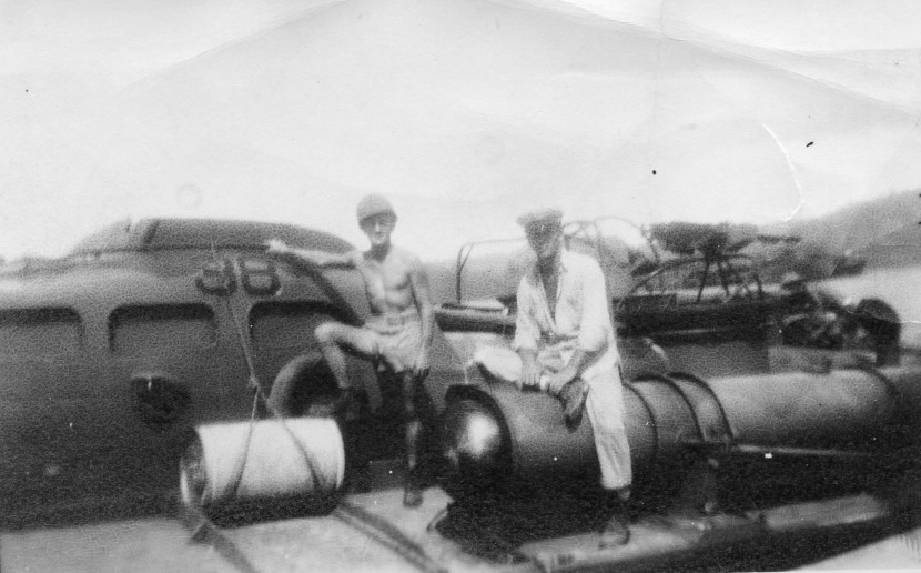
Whatever it was, it was clearly temporary. Other boats that installed this gun used a more substantial mounting. Not sure where I got this photo but if the 109 had survived I expect this is more like what would have happened with the 37mm. If ever build this boat again it will NOT have the gun on the deck.
[image]https://farm5.staticflickr.com/4749/25428319657_73a0a8bb83_b.jpg[/image]
David Waples
Posted By: David Waples | Posted on: Feb 16, 2018 - 5:43am
Total Posts: 1679 | Joined: Jan 2, 2007 - 9:55pm
In my opinion the way the mount was set up, when they returned, they probably would have put reinforcement planks on the backside of the deck and used large U bolts through the planks and deck. In this configuration, I can only see it being useful for shore bombardment, by maneuvering the boat into firing position and letting it fly,
As for barges, with its slow rate of fire, you could only get a few inaccurate rounds off when closing the target, because of either all the maneuvering the boat would be doing, or closing to board,once your too close, it couldn't depress enough to be useful.
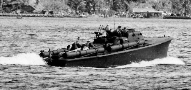
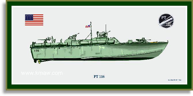
I think Dave's photo came around pretty quick after 1 August 1943, it was the only real way to make this weapon somewhat useful. A few boats had this weapon, but I really don't know which ones. The below artists rendering of PT 116 maybe just his opinion, the two photos I have of PT 116(maybe they were taken before it was mounted, I don't know) do not show a 37mm;
Regardless of how it was mounted, it didn't stick around long. Jan 1944 photos of RON 10 boats at Green Island show M4 37mm Automatic Guns mounted.
Take care,
TED
P.S. Didn't CDR Kelly's barge killer landing craft mount a 37mm M6 off a Dodge WC-55?
Posted By: TED WALTHER | Posted on: Feb 16, 2018 - 6:26am
Total Posts: 3059 | Joined: Oct 16, 2006 - 7:42am
Thanks Dave, I think the question answer if not resolved is strongly leaning towards wheels on.
Posted By: Jeff D | Posted on: Feb 16, 2018 - 7:44am
Total Posts: 2200 | Joined: Dec 21, 2006 - 1:30am
Over on SteelNavy, Steve Sobieralski has an insightful take on the wheels/no wheels question. [url] http://members.boardhost.com/Warship/msg/1518795507.html[/url]
Al
Posted By: alross2 | Posted on: Feb 16, 2018 - 8:55am
Total Posts: 993 | Joined: Oct 30, 2006 - 8:19pm
Interesting...
Not real crazy about the split hull and insert pieces... Kind of disappointed the details on the sides of the charthouse are molded on and not separate pieces...
My initial thoughts stand -- I'd be using some of the updated parts in this new kit to dress up the standard old Revell 80' Elco kit, particularly the twin-.50 turrets, limit rails and guns, the depth charges and cradles, the torpedo tubes, the port cockpit armor/splash shield, the engine room hatch, and a few other parts.
I'm a little taken aback, however, by a couple of the prices for this kit I've seen on Ebay -- $40 and $50! No way, Jose. I'll wait for a (hopefully) more reasonable price on Amazon.
Posted By: Drew Cook | Posted on: Feb 16, 2018 - 10:46am
Total Posts: 1306 | Joined: Oct 19, 2006 - 10:44am
Waiting or the aftermarket (later boat conversion) parts to appear will be worth the wait.
Jeff
Posted By: JBG327 | Posted on: Feb 16, 2018 - 4:30pm
Total Posts: 74 | Joined: Sep 29, 2012 - 2:40pm
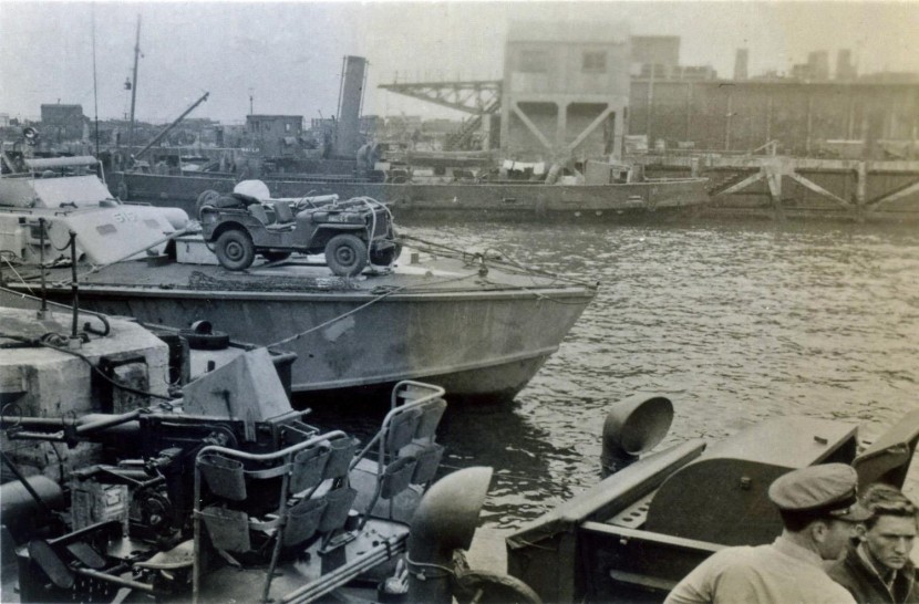
Here's an example of how they secured a heavy wheeled object to the foredeck albeit it probably wasn't secured as well as the 37mm which was heading out on a combat mission. Looks like planks were used under the wheels to spread the load and as wheel chocks, can't tell if any chains were also used to secure the Jeep to the planks. A larger version is here: [url]https://i.imgur.com/M5vEK25.jpg[/url]
Posted By: Jeff D | Posted on: Feb 17, 2018 - 10:41am
Total Posts: 2200 | Joined: Dec 21, 2006 - 1:30am