The PT Boat Forum
http://www.ptboatforum.com/cgi-bin/MB2/netboard.cgi
ģ Forum Category: PT Boats of WWII
http://www.ptboatforum.com/cgi-bin/MB2/netboard.cgi?cid=101&fct=showf
ģ Forum Name: PT Boats - General
http://www.ptboatforum.com/cgi-bin/MB2/netboard.cgi?fct=gotoforum&cid=101&fid=102
ģ Topic:
103 class hull outlets
http://www.ptboatforum.com/cgi-bin/MB2/netboardr.cgi?cid=101&fid=102&tid=3099
Hi all,
Newbie question. Sorry if this has cropped up before, but I am looking for information on the various hull side outlets on the early 103 class boats. I am building the Italeri 1/35 109 and I am comfortable with the D shaped fairing and round holes near the chine on the bow, and the two D shaped outlets just below the forward torpedo pivot. I cannot see evidence of the three other round outlets near the stern as shown in the kit. Does anyone here know of a drawing of the side outlets? I have trawled the internet and other references with no result so far.
Many thanks,
Stu Hurley
Posted By: Stuart Hurley | Posted on: Mar 19, 2013 - 3:35am
Total Posts: 255 | Joined: Mar 19, 2013 - 3:32am
Hi Stu,
Here are some of the best hull photos I've found because the color is so light making it easier to pick out detail. Hopefully somebody will post some good factory drawings. The ones I have are not clear enough to make a definitive call. Here are photos of PT-103 and PT-117 that may help provide some clues.
[IMAGE]http://i108.photobucket.com/albums/n27/David_Waples/PT%20BOATS/Image6_zps8d1c1980.jpg[/IMAGE]
[IMAGE]http://i108.photobucket.com/albums/n27/David_Waples/PT%20BOATS/IMG_0004_zpsf728f40f.jpg[/IMAGE]
[IMAGE]http://i108.photobucket.com/albums/n27/David_Waples/PT%20BOATS/IMG_0003_zps2abca264.jpg[/IMAGE]
[IMAGE]http://i108.photobucket.com/albums/n27/David_Waples/PT%20BOATS/IMG_0001_zpsbe6a744e.jpg[/IMAGE]
[IMAGE]http://i108.photobucket.com/albums/n27/David_Waples/PT%20BOATS/IMG_0002-1_zps56d054e5.jpg[/IMAGE]
[IMAGE]http://i108.photobucket.com/albums/n27/David_Waples/PT%20BOATS/IMG_zps4f700376.jpg[/IMAGE]
Dave
David Waples
Posted By: David Waples | Posted on: Mar 19, 2013 - 5:49am
Total Posts: 1679 | Joined: Jan 2, 2007 - 9:55pm
Hello again David,
Many thanks. These are a great help. They certainly do not show the three round outlets towards the stern and there seems to be a couple of extra outlets on the port side midway down which are puzzling me.
Regards,
Stuart
Posted By: Stuart Hurley | Posted on: Mar 19, 2013 - 6:41am
Total Posts: 255 | Joined: Mar 19, 2013 - 3:32am
Here's an outboard profile showing the starboard side outlets, scaled to 10 pixels per inch: [url]http://www.pt103.com/images/asst/BureauOfShipsOutboardProfilePlan496536trimmed_Scaled.jpg[/url] I don't think there's a similar view of the port side though... nor do I know if the drawing I posted shows all of them on the starboard side. Your best bet would be the Elco drawing DVD and a lot of .pdf viewing. The bottom also had a number of inlets and outlets. I'm sure not looking forward to digging them all up for my pt103 project.
Check out the parts catalog Dick has made available for download on this site. It shows locations of a number of inlets and outlets for the salt water system, toilets, sinks, bilge system, fuel vent and drain, etc.
Posted By: Jeff D | Posted on: Mar 19, 2013 - 11:30am
Total Posts: 2200 | Joined: Dec 21, 2006 - 1:30am
I am not certain, but I would venture a guess that these outlets you speak of are for the vent and overflow of gasoline from the fuel tanks. I say this because we have similar fitttings on the hull of Higgins PT658. The fittings seem to be in the general proximity of the fuel tanks. I know that Dr Al Ross would know for sure. Jerry
Jerry Gilmartin
Posted By: Jerry Gilmartin | Posted on: Mar 19, 2013 - 12:08pm
Total Posts: 1473 | Joined: Oct 8, 2006 - 11:16pm
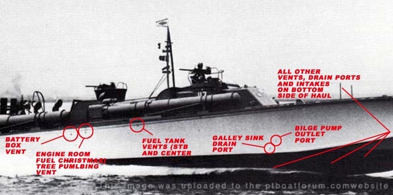
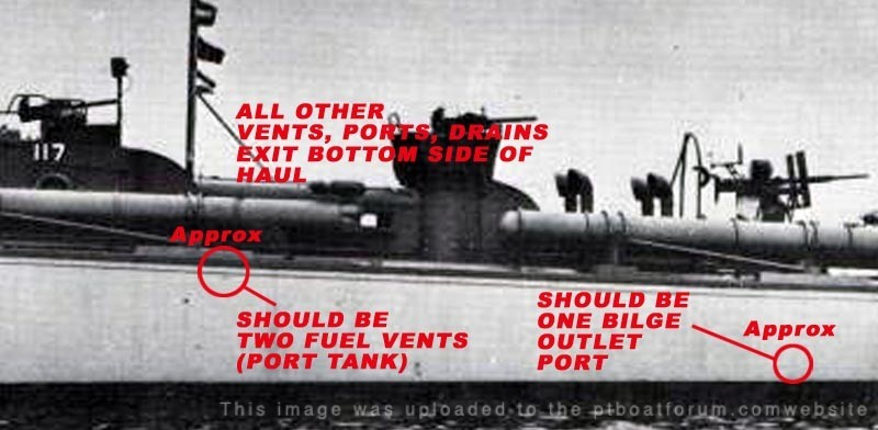
Several years ago I researched the Elco blueprints to determine which items indicated on the profile view drawings were actually ports being used. I reviewed the drawings that lead to the following discoveries, as indicated on the marked up photos below. Drawings reviewed were all Bilge Plumbing, Fuel Tank/Line Vents, Water Plumbing, Battery Box Vent. Many of the Plumbing lines such as, Toilets, Lavatory Sinks, Fuel Drain, Engine Room seawater Cooling Devices intakes and outlets, some Bilge Drain outlets, exit on the underside of the haul.
[image]http://i130.photobucket.com/albums/p249/ptboats/PT-103-OUTLETS.jpg[/image]
[image]http://i130.photobucket.com/albums/p249/ptboats/PT-103-OUTLETS2.jpg[/image]
Posted By: Dick | Posted on: Mar 19, 2013 - 12:12pm
Total Posts: 1417 | Joined: Aug 27, 2006 - 6:36pm
Nice work Dick, that will come in handy later!
Stu, I saw on the Model Shipwrights site that you are going to replicate the 109 on the Stanton. Here's a higher res image that you might find helpful: [url]http://www.pt103.com/images/ptpics/Photo_Scan_PT_109_Ferried_Stern.jpg[/url]. It's really hard to tell if it is all the same color or not.
Gene's PT King site shows the 103 and 105 being shipped out with the chart house, bridge, and maybe the torpedo tubes a lighter color than the deck. He used to have a closer image of the 105 that very clearly showed it but I can't find it anymore. You could see overspray(?) onto the deck, and what appears to be the same lighter color on the deck under the torpedo tubes. It's still visible on the images on this page though: [url]http://pt-king.gdinc.com/PTsquadronfive2.html[/url] I can't pick the color difference out on the 109 shot I posted though.
Posted By: Jeff D | Posted on: Mar 19, 2013 - 12:25pm
Total Posts: 2200 | Joined: Dec 21, 2006 - 1:30am
Dick, how do I add the signature "You got questions? I got confusion."
Posted By: Jeff D | Posted on: Mar 19, 2013 - 12:29pm
Total Posts: 2200 | Joined: Dec 21, 2006 - 1:30am
I'm assuming you mean Italeri parts PH22? On the hull, these outlets are all in the engine compartment. I've been looking over the schematics in the ELCO Parts Manual, but haven't found them yet. I think the forward one is the battery box vent on Dick's annotatted photo.
Al
Posted By: alross2 | Posted on: Mar 19, 2013 - 1:41pm
Total Posts: 993 | Joined: Oct 30, 2006 - 8:19pm
It just never ends, the things you continue to learn about the boats. Nice job Dick pointing out what each one is............
Posted By: Frank Andruss | Posted on: Mar 19, 2013 - 6:45pm
Total Posts: 3964 | Joined: Feb 9, 2007 - 11:41am
Thanks for stepping up guys! Great information as always. I agree with Frank. Always something new to learn here.
Dave
David Waples
Posted By: David Waples | Posted on: Mar 19, 2013 - 7:21pm
Total Posts: 1679 | Joined: Jan 2, 2007 - 9:55pm
Wow, Great response, and thanks to everyone who lent a hand.
Best regards,
Stu[:-cheers-:]
Posted By: Stuart Hurley | Posted on: Mar 20, 2013 - 1:07am
Total Posts: 255 | Joined: Mar 19, 2013 - 3:32am
Glad you found us useful Stu.
Maybe one is the auxiliary generator exhaust Al? I dug through the DVD drawings but could only find rough location details for PT 565-612 (ELCO_Roll_5535-3_72SCAN_00255.pdf).
Posted By: Jeff D | Posted on: Mar 20, 2013 - 3:57am
Total Posts: 2200 | Joined: Dec 21, 2006 - 1:30am
Dick, could you please repost the hull outlet images you did? Thank you sir, Mike is asking about them.
Posted By: Jeff D | Posted on: Mar 17, 2021 - 5:29am
Total Posts: 2200 | Joined: Dec 21, 2006 - 1:30am
Nevermind Dick, I think these are the ones:
Posted By: Jeff D | Posted on: Mar 17, 2021 - 6:31am
Total Posts: 2200 | Joined: Dec 21, 2006 - 1:30am
Hey Jeff . . .
Thanks for find them and posting them.
Dick . . .
Posted By: Dick | Posted on: Mar 17, 2021 - 11:04am
Total Posts: 1417 | Joined: Aug 27, 2006 - 6:36pm
Happy to help. Thank you for researching and making them Dick! That must have been like untangling a bowl of spaghetti.
Posted By: Jeff D | Posted on: Mar 18, 2021 - 7:51am
Total Posts: 2200 | Joined: Dec 21, 2006 - 1:30am
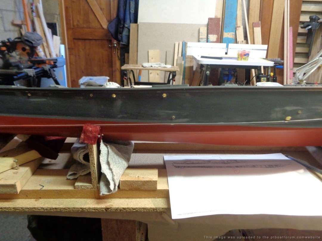
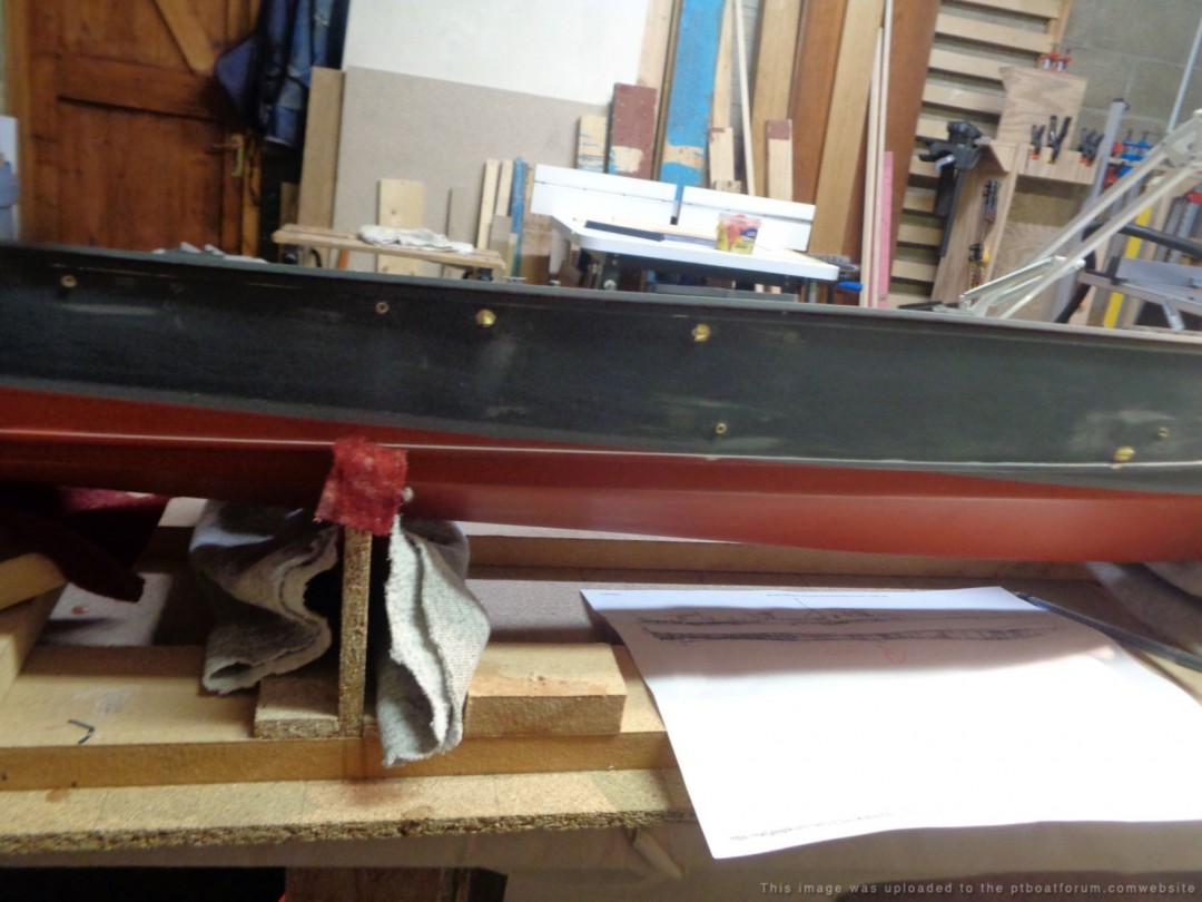
Drains I went off a couple drawing from Jeff D and a photo from Dick. Basically, this is my best guess.
Could the forum have a look any comments & corrections would be helpful?
Grady
Posted By: Grady | Posted on: Mar 29, 2021 - 5:34am
Total Posts: 157 | Joined: Oct 2, 2018 - 8:04am