| Author |
Topic: Toe rails for the new Revell Elco 80 |
|
SteveS156

New Member
|
  
 Posted on: May 12, 2018 - 5:42am
|
Hi, Jeff. As your photos show, there is no support wax in the scallops. I guess these are just beyond my modeling skills. Thanks for your response.
Steve
SteveS156 |
Total Posts: | Joined:
Unregistered | IP
Logged
|
|
smallwi

Advanced Member

|
 Posted on: May 16, 2018 - 12:29pm
|
Jeff,
These are really nice parts. I think there is confusion created by the base that is printed along with the parts. Now, I just need to figure out how to separate the parts from the base.
Bill
Bill Smallshaw |
Total Posts: 134 | Joined:
Jun 21, 2007 - 3:02pm | IP
Logged
|
|
Jeff D

Moderator

|
 Posted on: May 16, 2018 - 3:49pm Posted on: May 16, 2018 - 3:49pm
|
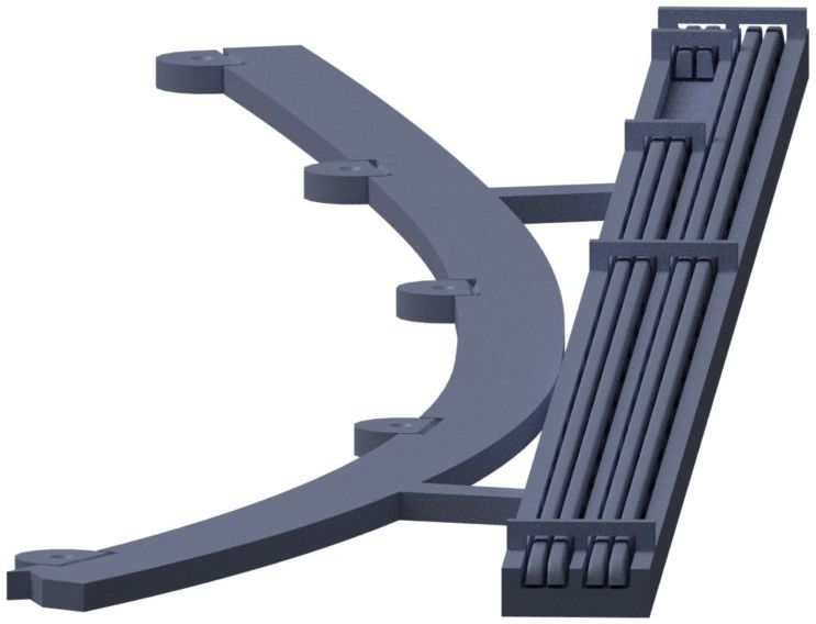
Hi Bill, thank you! There are actually 2 sets in the channel, 1 solid and 1 with cutouts for the depth charge racks. Note that it is not where Revell puts the depth charges, it is farther back. I need to clarify the instructions.
The rails are not attached to the channel, they are held in place by 3 small bars going across the top. I was able to snap the bars off with my fingernail. Wiggle the top of the rails with a fingertip and / or / run a thin knife blade along the rails then push up slightly from the bottom at the pins with a toothpick or other small tool to loosen them up if needed. The ones that I removed came out pretty easily.
Dave pointed out a mistake I made in the jig, there is no hole for the molded in deck cleats so it can't sit flush with the deck.
Here's the instructions I had up before removing the part from view:
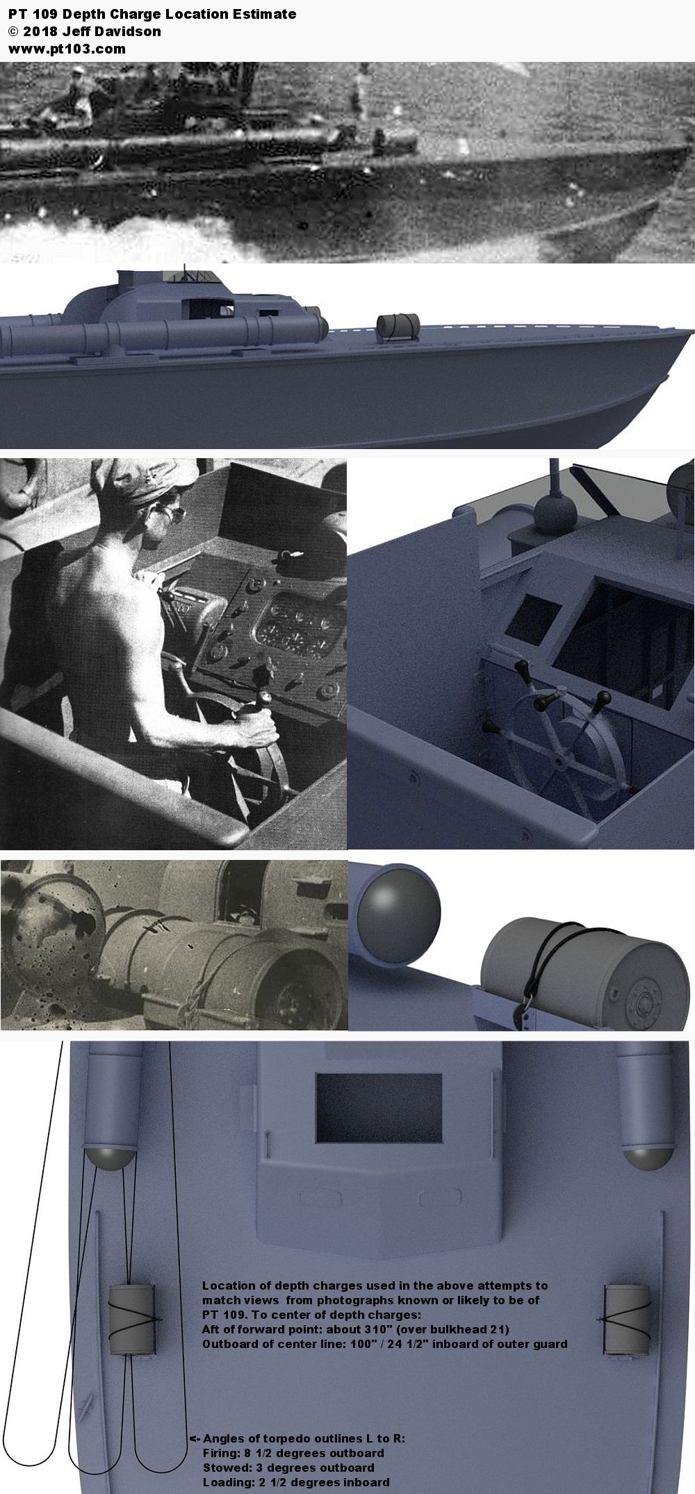
This model is the toe / foot rails for an 80' Elco PT boat. It is made to Elco drawings and features accurately spaced pedestals between scallops. The pedestals are located over the boat's frames and bulkheads which means they are almost all differently spaced due to curvature and different frame / bulkhead spacings. The rails have 5 mounting pins and a jig for drilling their mounting holes. Included are full rails and a set with gaps for the depth charges mounted on PT 109. For the depth charge locations on PT 109, I came up with a different location than what the 2018 Revell kit has based on available images of PT 109. Please see here: http://www.pt103.com/images/asst/PT_109_Depth_Charges_Location_Estimate.jpg
Preparation
The first step is to clean all parts thoroughly. Handle very carefully as the plastic is brittle. Please see the guide and links here: http://www.pt103.com/3D_Printed_PT_Boat_Parts.html. For best painting results be sure to follow cleaning with a UV cure from a lamp with the correct output, or the sun.
Clip off mounting jig.
Clip off the retainers above the rails.
Carefully run a thin blade tip along the side of the rails to be sure they are free. Carefully push up the rails slightly from the bottom at the mounting pin locations. Do not attempt to remove the rails until all pins have been loosened.
Installation
Measure 1/3 (24 full scale inches) back from the bow and draw a line at a right angle to the boat's center line.
Align the notch on the jig with this line and tape into place. Make sure the outer edge of the jig is even with the outside edge of the deck. See the part render image above.
Drill mounting holes. Check the rail fit, the pins are very fragile so do not force them.
To mount the rails without drilling holes, you may also use the jig without the hole guides. The inboard edge of the jig is 0.155 (11 1/8 full scale) inboard from the outside edge of the deck, and even with the outboard edge of the rails. Carefully snap or cut off the half round ears of the mounting jig, and remove the pins from the rails. Draw a guide line along the inboard edge of the guide or use it for placement while gluing.
|
Total Posts: 2200 | Joined:
Dec 21, 2006 - 1:30am | IP
Logged
|
|
smallwi
Advanced Member
|
Posted on: May 20, 2018 - 5:08pm
|
Jeff,
These are really nice parts. I think there is confusion created by the base that is printed along with the parts. Now, I just need to figure out how to separate the parts from the base.
Bill
Bill Smallshaw |
Total Posts: 134 | Joined:
Jun 21, 2007 - 3:02pm | IP
Logged
|
|
Jeff D
Moderator
|
Posted on: May 21, 2018 - 6:07am
|
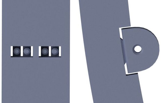
Thank you Bill! I did a few renders to help see how the little buggers sit in the channel. The right set is the full rails, the left set has a section cut out for the depth charge chutes. The top image shows the retaining bars across the tops that are removed to get the rails out. The rails are not attached to the channel. I was able to snap the bars off with my fingernail. Wiggle the top of the rails with a fingertip. you should be able to see them move a bit. If not, run a thin knife blade along the rails. The second image is a view from the bottom showing the holes the pins stick through. Working from one end to the other, gently push the ends of the pins just a little bit to get the rails loose. Dave had some trouble with them sticking, if you have an ultrasonic cleaner it might help loosen the rails. Thanks to Dave's testing these for me I'm going to try to come up with a better design that won't be affected as much by Shapeways sometimes spotty cleaning. His rails also came from Utah, possibly from one of SW's partners.
|
Total Posts: 2200 | Joined:
Dec 21, 2006 - 1:30am | IP
Logged
|
|
smallwi
Advanced Member
|
Posted on: May 21, 2018 - 7:13am
|
Jeff,
These are really nice parts. I think there is confusion created by the base that is printed along with the parts. Now, I just need to figure out how to separate the parts from the base.
Bill
Bill Smallshaw |
Total Posts: 134 | Joined:
Jun 21, 2007 - 3:02pm | IP
Logged
|
|
David Waples
TOP BOSS

|
Posted on: May 25, 2018 - 4:35am
|
Ah so! A picture is worth a thousand words. The rails aren't attached to the base at all, except by the wonderful wax material that supports the print.
It seemed like on the print I had that the forward end was attached to the base with resin. The very end with the pin clearly broke off just after the pin. Is it possible to add a little more separation? Additional cleaning is really key. And I think post cleaning after separation is important as well.
I intend to knock this out over the weekend. Stay tuned.
Dave
David Waples |
Total Posts: 1679 | Joined:
Jan 2, 2007 - 9:55pm | IP
Logged
|
|
Jeff D
Moderator
|
Posted on: May 25, 2018 - 7:14am
|
Yes I plan on a total redesign so the part floats in a cage with plenty of clearance. Also with drainage holes on the bottom. I see I got lucky with the test print I did. Thank you again David for all the help you've given me designing and testing various parts!
|
Total Posts: 2200 | Joined:
Dec 21, 2006 - 1:30am | IP
Logged
|
|
smallwi
Advanced Member
|
Posted on: Jun 1, 2018 - 11:17am
|
Jeff,
Sorry about the multiple posts previous, an anomaly thanks to Safari browser :-). Thanks posting the instructions, clarifies some mysteries for me, like �now, what am I supposed to do with this jig?� :-). Hopefully my Revell kits have arrived this week and I can contemplate actually doing a build rather than collecting stash material. Thanks to your parts I almost feel like I did 46 years ago when my father brought home the original PT 109 kit. Which by the way started my complete obsession with palstic ship models.
Bill
Bill Smallshaw |
Total Posts: 134 | Joined:
Jun 21, 2007 - 3:02pm | IP
Logged
|
|
Jeff D
Moderator
|
Posted on: Jun 2, 2018 - 5:34pm
|
Very cool Bill, I hope you enjoy the build!
|
Total Posts: 2200 | Joined:
Dec 21, 2006 - 1:30am | IP
Logged
|
|
|


