| Author |
Topic: Elco 77' Torpedo Tube Training Gear |
|
David Buck

TOP BOSS

|


 Posted on: Oct 29, 2014 - 12:30am Posted on: Oct 29, 2014 - 12:30am
|
Hi, Anyone have any photos of the bracket the threaded rod ran through that was fitted to the underside of the torpedo tube?
21" early or late period if they did change it?
Ta.
D.buck |
Total Posts: 332 | Joined:
May 4, 2008 - 2:59am | IP
Logged
|
|
Andy Small

MASTER

|
Posted on: Oct 29, 2014 - 7:35am
|
Here some more close ups of PT20 and the last is a view of a connecting crank shaft just resting on a hand rail.
Andy


|
Total Posts: 261 | Joined:
Nov 20, 2013 - 9:04pm | IP
Logged
|
|
Dick
Moderator

|
Posted on: Oct 29, 2014 - 10:12am
|
Andy - Great shots, specially of the rearview of the engine room trunk clearly showing the right-angle drive and the crank thru the trunk cabin bearing into the aft end of the engine room. Also the storage of the connecting drive rods on the trunk cabin.
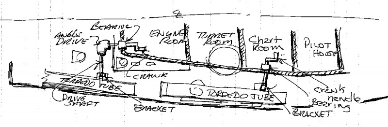
Dave - It is pure speculation on my part and purely by the examination of the engineering drawings that I have concluded that originally it must have been planned to train the tubes from within the cabin. The froward tube mechanically operated from within the Chart room section of the cabin, and crank handle would have been about waist high for easy operation. In addition the aft tube would have been deployed from within the Engine room at a shoulder on-up height for the crank access and operation.
I’m sure this proved to be problematic after a bit, specially for boat operations in more warmer climates, As with the removal of the turret domes, I’m sure the crew came up with a ratcheting wrench or at least an open end wrench with a long handle for better torque. Not sure how much effort would need to be provide to actuate the drive screw as to rotate the tube in and out. Clearly the intended crank used outside on the deck would have been a real knuckle buster, even it would have fit in that type of operation.
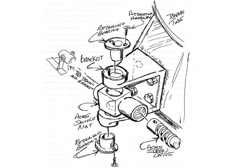
Dave & David - I’ve include some rudimentary sketches to illustrate the original operation of deployment. Dave, you were correct as to the “last” bracket. After studying the drawings for sometime I finally realized the bracket was used to mount and retain the swivel nut used with the drive screw. It was attached to the inside edge of the tube support. This attachment allows the tube assembly to move along the drive screw as it rotates in place.
David - We only have a few of the drawing Mods that tell us about the timing. For know at least, we know that in a Mod 2 drawing it shows the details of an 90 degree-up Training Gear Box (May 1942, drawing changed July 1942 & approved by the Gov�n Nov 1942.
Thanks all,
Dick . . . .
(Richard J. Washichek)
PLAN VIEW SKETCH OF ORIGINAL CRANKING PLAN FOR TUBE POSITIONING:
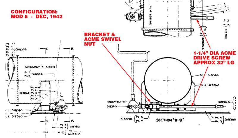
CROSS SECTION OF TORPEDO TUBE - MOD 5:
MY SKETCH OF BRACKETS ATTACHMENT, SWIVEL NUT AND DRIVE SCREW WITH ACME THREAD:
|
Total Posts: 1417 | Joined:
Aug 27, 2006 - 6:36pm | IP
Logged
|
|
Jeff D
Moderator

|
Posted on: Oct 29, 2014 - 1:07pm
|
This thread just keeps getting better, thanks for the PT 20 closeups Andy and the drawings Dick!
|
Total Posts: 2200 | Joined:
Dec 21, 2006 - 1:30am | IP
Logged
|
|
 |
Jerry Gilmartin |
TOP BOSS

|
Posted on: Oct 29, 2014 - 4:18pm
|
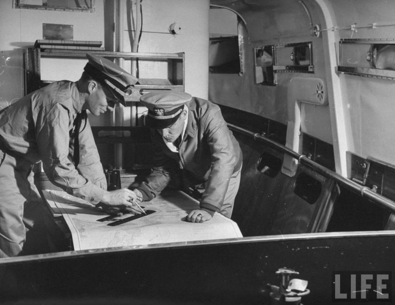
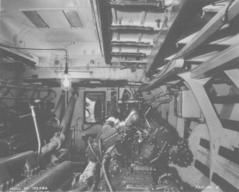
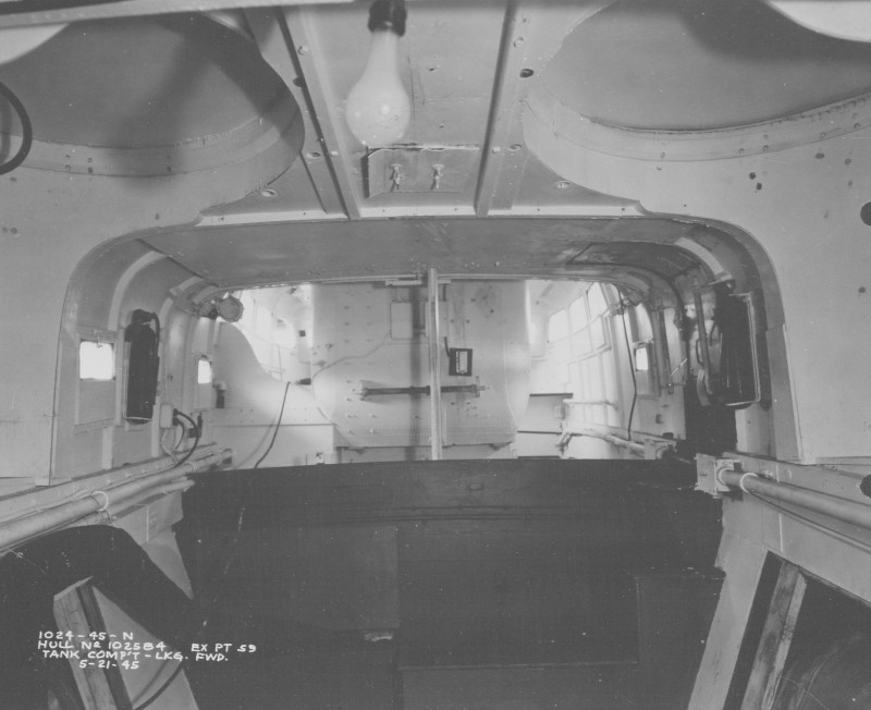
I just wanted to post these from Gene Kirklands PT King Website, they show the hubs and possibly crank handle inside a 77' Elco.
Engine room trunk see two round hubs and brackets over them to hold the removable crank handles
Inside chart house, see two cylindrical hubs on either bulkhead
Jerry Gilmartin
PT658 Crewman
Portland OR
|
Total Posts: 1472 | Joined:
Oct 8, 2006 - 11:16pm | IP
Logged
|
|
alross2
TOP BOSS
|
Posted on: Oct 29, 2014 - 5:38pm
|
I haven't looked, but some answers might be found in the 70' drawings. PT 20 was the transitional boat and, at least initially, retained some of the features of the 70' boat. For instance, there are photos of the 20 boat running trials with the "birdcage" turret domes of the 70' boats. In the photo on page 1, you can see that the trunk cabin end has the sharp-edge corner of the earlier boats. The photo of the boats under construction shows the standard rounded corner of the 77' boats. Might be worth a look.
Al
|
Total Posts: 993 | Joined:
Oct 30, 2006 - 8:19pm | IP
Logged
|
|
Patrick Matthews

New Member
|
Posted on: Oct 29, 2014 - 5:55pm
|
OK, two Q's:
1. I would have killed for some of those photos when I was first trying to figure out the deck arrangements on my PT-41! But never saw those detail images... where do they come from?
2. What was the saddle-block for, as seen on the PT-20 shot?
Patrick Matthews
Matthews Model Marine
http://matthewsmodelmarine.wordpress.com/ |
Total Posts: | Joined:
Unregistered | IP
Logged
|
|
Andy Small
MASTER
|
Posted on: Oct 29, 2014 - 8:29pm
|
The photo of PT-45 on page 41 of Early Elco PT Boats, shows a clear view of the forward port cabin hub with the deck stiffener cutout.
Andy
|
Total Posts: 261 | Joined:
Nov 20, 2013 - 9:04pm | IP
Logged
|
|
David Buck
TOP BOSS
|
Posted on: Oct 30, 2014 - 3:31pm
|
Hi Dick,
Your sketch and your photo in your first post have helped a lot thanks .
D.buck |
Total Posts: 332 | Joined:
May 4, 2008 - 2:59am | IP
Logged
|
|
Jeff D
Moderator
|
Posted on: Jun 22, 2020 - 4:57am
|
Bump for a resurrected thread thanks to Dick fixing most image links. Thanks Dick!
|
Total Posts: 2200 | Joined:
Dec 21, 2006 - 1:30am | IP
Logged
|
|
|