| Author |
Topic: Higgins cut-away drawing update |
|
Dick

Moderator

|


 Posted on: Sep 1, 2008 - 11:45pm Posted on: Sep 1, 2008 - 11:45pm
|
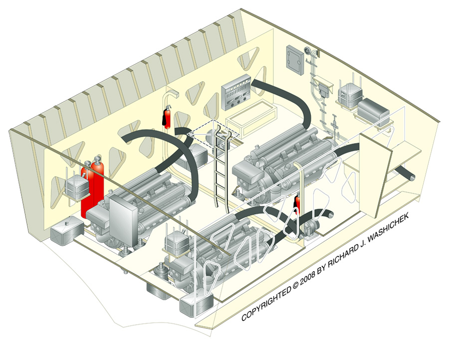
Another installment for the Higgins cut-away. This time it's the Engine Room - its mansion size compared to the 80' ELCO.
Please enjoy,
Dick . . . .
|
Total Posts: 1417 | Joined:
Aug 27, 2006 - 6:36pm | IP
Logged
|
|
Dick
Moderator
|
Posted on: Sep 5, 2008 - 1:58pm
|
Another update on Higgins drawing - yeah again. . .
Completed the Aft Fuel Tank compartment, the Storage compartment and the Lazarette. Then made the below composite assembly. With all of the compartments assembled, there is a lack detail of each individual unit, but art does provide a good overall view of below deck. Like my ELCO project there will be independent views of the compartment allowing the detail of each to be readily seen.
Still having a lot of angst over the actual configuration of this series of boats. As mentioned in earlier posts, Higgins drawing don't match the great Higgins photos at Gene Kirkland's PT King website. Even though the photos show the same series of boats in various construction stages, the configuration is quit different then those shown on the drawings. Strangely one photo show PT-88 configured differently then a photo two months later (the more familiar look), ready to be launched. Oh well, I guess I'll take some Alka Seltzer for "Indecision".
Dick . . . . .

|
Total Posts: 1417 | Joined:
Aug 27, 2006 - 6:36pm | IP
Logged
|
|
Frank J Andruss Sr
TOP BOSS

|
Posted on: Sep 5, 2008 - 3:26pm
|
Dick
I noticed in the spacious engine room of the Higgins that I could not locate an area for the Engineer. Where did he sit while the boat was underway......
|
Total Posts: 3497 | Joined:
Oct 9, 2006 - 6:09am | IP
Logged
|
|
 |
Jerry Gilmartin |
TOP BOSS

|
Posted on: Sep 5, 2008 - 5:25pm
|
Hi Frank!
The Motor Mac on watch in the engine room would stand just in front of that ladder because the reach rods for the shift levers all can be operated from that position. The Motor Mac would watch the 3 engine order telegraph arrows (located just above the gageboard on the forward bulkhead) and then shift engines according to the arrow positions. Each engine takes about 75 foot-pounds of force in order to shift it, so it may have been easier to come up with that much force when you were standing. Also, there was so much room in the Higgins Engineroom compared to the Elco, I imagine the watchstanders could keep themselves occupied by playing a quick game of horseshoes or maybe even basketball while they were down there! The center engine shifter reach rod is longest, and travels under the deck on the stbd side of the engine and then comes up right next to the ladder. Bill Maloney has posted some excellent photos of the inside of the engineroom on PT-796 http://www.williammaloney.com/Aviation/Aviationindex.html and the one labeled "05TransmissionGearLever" shows what I am talking about with the lever. So to answer your implied question, NO, the Higgins MotorMacs didnt have a cushy seat to sit on like those on the Elco's! Ha ha! Jerry
Jerry Gilmartin |
Total Posts: 1472 | Joined:
Oct 8, 2006 - 11:16pm | IP
Logged
|
|
Frank J Andruss Sr
TOP BOSS
|
Posted on: Sep 6, 2008 - 2:11am
|
Thanks Jerry
I bet those boys had some stiff legs having to stand most of the time while underway. Checked out the photo's which really do not show the spacious space afforded the engineers. Maybe you have one of your boat that has a better look at the space occupied by the massive packards. That's one thing that Elco did not do. They left a cramped engine room, but presented a wonderful living space upfront. Little did they know that most time spent would be on deck, and most of the time ( in the Pacific ) it was just too hot to sleep below. I guess that was the trade off, having more comfort for the crew.......
|
Total Posts: 3497 | Joined:
Oct 9, 2006 - 6:09am | IP
Logged
|
|
Dick
Moderator
|
Posted on: Sep 6, 2008 - 7:57am
|
Jerry . . .
Thanks for great insight on the Higgins engine room operations.
Frank . . .
I stole these photos from Jerry and gang at the Portland Groups website - some great shots of the engine room. Sorry Jerry for stealing the photos, I hope the group doesn't mind.
Below a photo collage from Portland Oregon's Save the PT Boat (PT-685) website:
http://www.savetheptboatinc.com/index.htm
Dick

|
Total Posts: 1417 | Joined:
Aug 27, 2006 - 6:36pm | IP
Logged
|
|
Frank J Andruss Sr
TOP BOSS
|
Posted on: Sep 6, 2008 - 9:24am
|
Dick
Thanks for the awesome shots of the engine room. Boy, it was spacious no doubt making for a happy enginer. Of course, thanks to Jerry and the gang for the pictures from the group.........
|
Total Posts: 3497 | Joined:
Oct 9, 2006 - 6:09am | IP
Logged
|
|
Dick
Moderator
|
Posted on: Sep 17, 2008 - 12:27am
|
Yes, another one of those annoying � �Higgins Project Update� � I have just finished the below deck image and the upper deck view. Still have to draw and explode-out the charthouse detail and add all the callout description text. Still haven't made my mind up what PT boat number and upper deck armament configuration to use. It seems the older I get the more indecision creeps in, but I have to make my mind up real soon. Also haven�t decided to keep it gray or change it to green like my earlier ELCO project. Any comments are welcome.
In other post I have discussed the interior arrangement, specifically when it comes to the aft Fuel Tank and Storage Compartments. I have a version, which illustrates the center compartment between the two aft tanks as a Crew�s Head and the storage compartment as a four bunk secondary Crew area. The current Generator and Compressor Fuel tanks in the center fuel compartment move to the outer hull wing areas, starboard and port of the aft fuel tanks. The Co2 Bottle remains but moved to the aft/port corner.
I also have a Higgins 625 Series top side drawn in pencil but not yet traced and colored in Illustrator. Will get to this after finishing the first Higgins.

Just as informative note, the original art is being drawn in Adobe Illustrator as line art. Most of the artwork was first plotted in isomeric and drawn in pencil then scanned as a Pict file and opened in Illustrator as a template. Where I then trace and add color to each and every component. A component can be as simple as a hull frame, it is made up of three separate sub-components (planes � front, side & top) and each one has to drawn and colored separately. Some of the components are drawn directly in Illustrator. The actual Illustrator art size is 62� x 62".
Since the drawings are lines, I have to import the Adobe Illustrator file into Photoshop and create an image file like the attached posted image above. The saved file gets manipulated to an appropriate size for this message board saved as a medium resolution J-peg (.jpg) file. The image displays pretty good but if printed it suffers greatly from the image manipulation to be sized reasonably small enough to post and load-up within a reasonable time frame.
Dick . . . .
|
Total Posts: 1417 | Joined:
Aug 27, 2006 - 6:36pm | IP
Logged
|
|
 |
TED WALTHER |
TOP BOSS

|
Posted on: Sep 17, 2008 - 5:35am
|
Dick;
You wrote: Prior to the self sealing tanks, �� armor plates were made as an exterior bolt-on item starting with PT 308-313 & 456-461. The kit consisted of four sets of plates, two sets on each side and bolted onto the exterior of the hull with 3� carriage bolts at Frames 22 thru 34 (Officers Qrt., Fuel Tank Area, & partial Engine Room) and Frames 42 thru 55 (Partial Engine Room, Aft Fuel Tank Area & Partial Storage Area (or Aft Crews Qrt)). I can�t imagine bolting on plates to the exterior hull. There was one install note that read: �All bolts thru sides of hull to be wound with a short piece of lamp wick or cotton soaked in caulkine compound,� I guess this keeps the 738 carriage bolts from leaking water thru the hulls side walls. The plates were mounted between the Guard Rail and Spray Rail/Chine and just above the muffler.
This is correct, PT 308 when I was on her at Franklin Timmons boatyard still had her 1/4" plates still on her sides. At the time I tought this was just some sort of patch, or something. I never realized this was part of the factory package.
Take care,
TED
|
Total Posts: 3059 | Joined:
Oct 16, 2006 - 7:42am | IP
Logged
|
|
| |
TED WALTHER |
TOP BOSS
|
Posted on: Sep 17, 2008 - 9:54am
|
Dick;
I posted photos of PT 308, which I took in October 1988. You can see the 1/4" armor plate in the one photo showing the portside very clearly.
take care,
TED
|
Total Posts: 3059 | Joined:
Oct 16, 2006 - 7:42am | IP
Logged
|
|
|