| Author |
Topic: Italeri 1/35 PT-105 Build - David Waples |
|
David Waples

TOP BOSS

|
  

 Posted on: Jun 24, 2013 - 7:17pm
|
Thanks Ted for pulling me off the cliff,
I want to make sure I have this right. If I'm understanding correctly the grating is surrounded by a coaming which basically keeps water out of the grating. Is that correct? Did one of the vets you spoke with tell you about the coaming and the grating at the helm?
I have no idea where Italeri got the idea of the grating and curious if you know of any reference that documents this.
Thanks again. Looking forward to hearing back from you.
Dave
David Waples |
Total Posts: 1679 | Joined:
Jan 2, 2007 - 9:55pm | IP
Logged
|
|
TED WALTHER
TOP BOSS

|
 Posted on: Jun 24, 2013 - 7:31pm Posted on: Jun 24, 2013 - 7:31pm
|
Dave;
All I have is, it makes sense. Yes it was the same size as the molded piece. All I have is in the diagrams. As you suggested, this item disappeared around PT 120-138. Charge on it is correct for your boat!!!!
Take care,
TED
P.S. this is not something that I would think John Iles would have really noticed, as you might have surmised, correct me if you think I am wrong, But, he was the kind of guy who just jumped in and did the mission. If you still are in question, you need to employ PTHQ and see if they have a photo showing this, within the applicable boat numbers.
|
Total Posts: 3059 | Joined:
Oct 16, 2006 - 7:42am | IP
Logged
|
|
Roy Forbes
TOP BOSS

|
Posted on: Jun 25, 2013 - 8:10am
|
I keep been hearing about this rubber mat lately. I never knew Elco replaced the wood grating and I wonder how well that rubber stood up to the heat and humidity in the South Pacific.
|
Total Posts: 371 | Joined:
Sep 5, 2012 - 4:57pm | IP
Logged
|
|
David Waples
TOP BOSS
|
Posted on: Jun 26, 2013 - 5:57am
|
Roy,
Look at the photos at the pt127.org web site. These are the only pictures I've ever seen of the cockpit floor and you can see matting. These are late war photos.
Dave
David Waples |
Total Posts: 1679 | Joined:
Jan 2, 2007 - 9:55pm | IP
Logged
|
|
David Waples
TOP BOSS
|
Posted on: Jul 6, 2013 - 5:36am
|
Okay, I just updated a previous slide. Don't do what I did by adding the cross bars. The hull needs some flexibility to secure the deck correctly. I think Stu had the best approach by supporting the underside of the deck with poles from sprue to give the deck some strength. Now I'm off to cut all that out.
Dave
David Waples |
Total Posts: 1679 | Joined:
Jan 2, 2007 - 9:55pm | IP
Logged
|
|
Kornbeef

New Member
|
Posted on: Jul 7, 2013 - 7:47am
|
David,
I fixed my hull/deck then pit a sprue post under the rear deck, I was going to do the same at the front then found some 10mm square basswood from a ancient failed wooden build, I used this to place a prop under the front deck then cut two long lengths and Cyano'd them either side of the slot in the deck and made props to push the deck up to achieve the desired angle. this effectively made the whole length stay uniform and allowed adjustment with everything in place. secures the props with cyano gel
Keith
Never to old to learn something
Doesn't stop me forgetting the obvious though |
Total Posts: | Joined:
Unregistered | IP
Logged
|
|
David Waples
TOP BOSS
|
Posted on: Jul 7, 2013 - 10:11am
|
Thanks Keith,
I think that's the approach I'm going to take as well.
Dave
David Waples |
Total Posts: 1679 | Joined:
Jan 2, 2007 - 9:55pm | IP
Logged
|
|
David Waples
TOP BOSS
|
Posted on: Jul 14, 2013 - 8:50pm
|
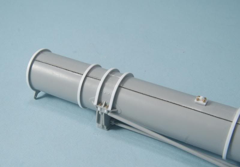
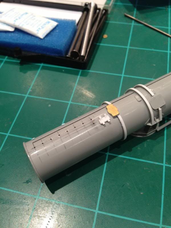
Some progress on the torpedo tubes....
I used Archer Fine Transfer arc weld beads .015 inch (.38 mm) wide to simulate the weld line that runs down the port side of the tubes. These are resin weld lines printed on decal film. You apply them like decals but they are 3D. Beautiful stuff!
In this picture you'll also see where I added the bolts and mounting detail which attaches the cross brace to the tube bracket (for lack of something better to call it). The nuts and bolts are scale brass and are beautifully made and easy to use. I secured them in place with Gator Grip PVA glue.
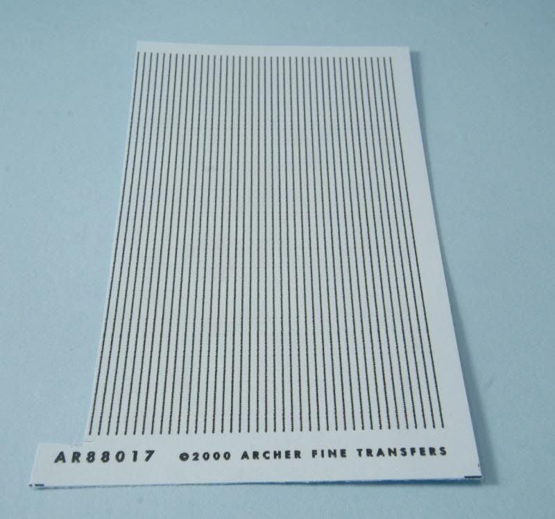
Here's a photo of the remainder of my weld lines.
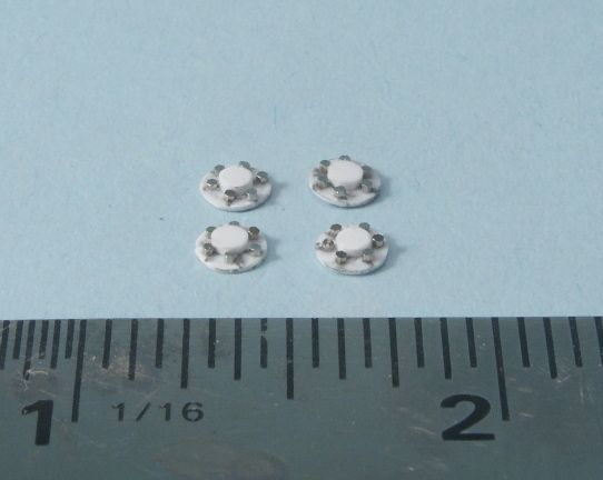
Now for the ridiculous. I'm improving the look of the tube combustion chambers by punching out discs and between them installing .7mm Simulated Hex Bolts Nickel Plated Brass from Scale Hardware. I used these because they were the only thing I could find that would fit between the plates without making the space in between too large. Would I do this again? No. For the next boat I will punch out .010 thick plastic with my punch set and glue them in the same pattern as I applied the bolts. The bottom line is that they're so small and sandwiched between the plates are hardly visible. It was fun, challenging, and looks good. But I think the plastic punches will look just as good, be less expensive, and easier to install.
Update: My concern with the nickel plated nuts was that they would not hold paint. I primed them with an automotive etching primer. Two things. First, once the primer was applied the hex shape was almost impossible to distinguish with visors. Second the primer still would not hold on to the nickel plating to my satisfaction. Solution for me will be to use a miniature punch set to create .06 diameter discs which will be secured with Gator Grip PVA. Punch set is ordered and on the way. I still like the brass hex nuts as shown in the photo below because they are very visible. I'm not concerned with them holding paint.
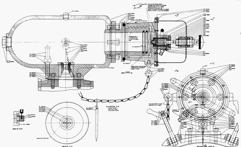
Here's the drawing of the combustion chamber for reference
David Waples |
Total Posts: 1679 | Joined:
Jan 2, 2007 - 9:55pm | IP
Logged
|
|
Bob Butler

MASTER

|
Posted on: Jul 14, 2013 - 11:58pm
|
David, I can't wait to see this boat when you finish.
|
Total Posts: 192 | Joined:
Mar 23, 2013 - 11:58am | IP
Logged
|
|
David Waples
TOP BOSS
|
Posted on: Oct 21, 2013 - 9:14pm
|
Finally making some progress back at the bench.
First some detail on the torpedo tubes.
Rivets were added to the back and top ends of the torpedo tubes based on the Elco drawings. I used Archer Fine Transfer rivet decals. I found that they went on beautifully over bare plastic. I used Micro Sol to snug them down. Micro Set is useless for these decals.
More to come on the tubes later.
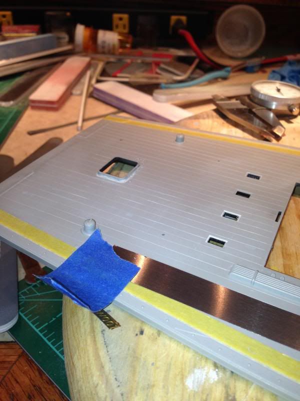
I've wanted to maintain the planking lines on the deck but I also wanted to remove the raised edges and correct the stern edge of the decking. I really liked the raised panel lines that Italeri added. They are the perfect dimension. However I realized that trying to repair those incredibly fine lines where I corrected the raised detail I wanted to remove was going to be impossible. The only way to do it was to scribe the lines into the deck. First I tried free hand with my favorite scribing tool from UMM USA. These tools have the ability to draw straight lines by pushing the tool. I found it was too difficult to make perfect lines and gave up on that. I had to fill in my errors with Mr. Surfacer 500. After sanding smooth, I moved on to the next technique which was to lay down a straight edge, tape in place, and scribe the lines in. The straight edge is very thin flexible metal. I used the Italeri lines as a guide and proceeded to carefully scribe the lines in. This is what I was looking for! By the way, the straight edge I'm using is also from UMM USA. They have the best tools! I've spent a couple of nights on it already and am about 1/3 the way to completion. After I sand down the deck slightly to remove what's left of the Italeri lines and add paint I should have the effect I'm looking for.
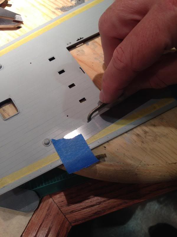
I think you can see that the lines are coming along nicely.

That's all for now. I have 4-5 more nights of scribing ahead of me.
Dave
David Waples |
Total Posts: 1679 | Joined:
Jan 2, 2007 - 9:55pm | IP
Logged
|
|
|