| Author |
Topic: Italeri kit dayroom front and rear walls |
|
Stuart Hurley

MASTER

|
  

 Posted on: Mar 26, 2013 - 2:21am
|
Hi all,
Can anyone confirm that the dayroon front and rear walls should be 90 degrees to the waterline, the same as the rear turret ? Looking at drawings I think this should be so.
I think this accounts for the odd appearance of the turret stagger in the kit when viewed from tthe starboard side. The turret itself is O.K. I reckon.
Best regards,
Stu
Best Regards,
Stu.
Measure twice, cut once.
|
Total Posts: 255 | Joined:
Mar 19, 2013 - 3:32am | IP
Logged
|
|
Jeff D

Moderator

|
 Posted on: Mar 26, 2013 - 5:31am Posted on: Mar 26, 2013 - 5:31am
|
They are Stu, as is the inner framework. Are the kit walls OK?
|
Total Posts: 2200 | Joined:
Dec 21, 2006 - 1:30am | IP
Logged
|
|
Stuart Hurley
MASTER
|
Posted on: Mar 26, 2013 - 5:50am
|
Hi, Jeff,
Unfortunately not then. The dayroom is all square. The front wall isn't too noticeable but the rear makes the turret stagger look wrong from starboard. I can see most people will leave this well alone. The rear wall is a fairly easy fix but the front is tricky as then there will be a discrepancy in the lenth of the cabin where it meets the cockpit steps etc. and then you may find the roof a little short as a result and it will all get worse from there. Fortunately the spray shields hide this area quite well
BTW did you see my question about the training cranks on the roof? On your partial drawing it would appear that the starboard side crank is mounted further aft than the port. They are opposite each other in the kit. Just wondered if this is correct. Sorry to keep sponging off you but my enquiring mind keeps finding stuff......
Best regards,
Stu
Best Regards,
Stu.
Measure twice, cut once.
|
Total Posts: 255 | Joined:
Mar 19, 2013 - 3:32am | IP
Logged
|
|
Jeff D
Moderator
|
Posted on: Mar 26, 2013 - 9:43am
|
Bummer Stu...
Stu, you are in no way sponging off me. I appreciate your going through the extra effort to get it right very much. I think it's a show of respect to the men that fought on them. I also appreciate your sharing your observances with us. So it's more like me sponging off you. :D I started my site to help modelers get it right, one particularly bad RTR R/C boat really set me off. After seeing what was available, it wasn't until I saw a plan drawn by Al Ross of http://www.coastalforcesplans.com that I saw what they really should look like. Then I bought most of the Elco 103 class drawings available at http://www.ptboats.org, but wasn't really happy using general arrangement drawings with little or no dimensional info. Then Dick gave me a copy of the Elco DVD... which caused me to happily trash most previous work.
I missed the crank question Stu. I noticed the difference of the torpedo tube crank mounts but don't have a satisfactory answer. I believe Italeri used the deck arrangement drawing which shows them even. For the most part the drawing is very accurate which leads me to guess they were moved. I used the specific crank stowage drawing which shows them staggered. It's one of the drawings the Navy didn't film very well but the placement dimensions were visible. The modification and application sections are almost illegible. A total guess would be that the starboard crank was moved back around the same time the day room hatch was hinged to the aft so that the hatch wouldn't sit on top of it when opened.
When modeling the cranks I was surprised at how few photos I had that show the mounted cranks. I guess because they were removed when roll off racks were installed. Maybe another board member can shed further light on this. This is about the only image I have of the mounted crank, it shows the stbd one and it appears to be moved back from where the deck arrangement drawing shows it:

Anyone know which boat that is?
|
Total Posts: 2200 | Joined:
Dec 21, 2006 - 1:30am | IP
Logged
|
|
Jeff D
Moderator
|
Posted on: Mar 26, 2013 - 9:57am
|
I checked the deck arrangement drawings, which I should have before, and see that the drawing for PT 372-383 and some 540's boats show the cranks staggered. It's still possible the move was made before these boats though. As always, images of boats are needed to verify.
|
Total Posts: 2200 | Joined:
Dec 21, 2006 - 1:30am | IP
Logged
|
|
Stuart Hurley
MASTER
|
Posted on: Mar 26, 2013 - 11:54am
|
Hi Jeff,
Thanks, very much. I will leave the kit as is then as I have changed the pads to represent the wooden blocks and bungee cord. I have carried out the modifications to the dayroom to introduce the rake and they were quite simple after all.They certainly improve the look. I will post some pictures when I get a chance, probably over at Todds thread which he kindly invited me to hijack occasionally.
Best Regards,
Stu.
Measure twice, cut once.
|
Total Posts: 255 | Joined:
Mar 19, 2013 - 3:32am | IP
Logged
|
|
Will Day
TOP BOSS

|
Posted on: Mar 26, 2013 - 1:05pm
|
@Jeff: I believe that's the 315 boat dummied up for a training film. (Right, Frank?)
Will |
Total Posts: 1955 | Joined:
Oct 8, 2006 - 4:19pm | IP
Logged
|
|
alross2
TOP BOSS
|
Posted on: Mar 26, 2013 - 3:27pm
|
Stuart,
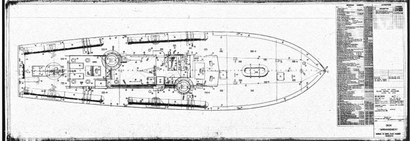
Here's the inboard profile for the iinitial series boats to illustrate the vertical nature of the frames, bulkheads, and deck structures..
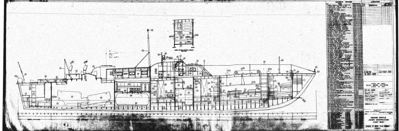
Same series, showing the placement of the speed wrenches for the torpedo tubes.
Al Ross
|
Total Posts: 993 | Joined:
Oct 30, 2006 - 8:19pm | IP
Logged
|
|
Stuart Hurley
MASTER
|
Posted on: Mar 26, 2013 - 5:13pm
|
Hi, Al.
Fantastic, many thanks, some pics over at Todds thread.
Best Regards,
Stu.
Measure twice, cut once.
|
Total Posts: 255 | Joined:
Mar 19, 2013 - 3:32am | IP
Logged
|
|
Drew Cook
TOP BOSS

|
Posted on: Mar 26, 2013 - 8:04pm
|
Will,
That's a still from the Warner Bros. documentary "Devil Boats."
Don't know which PT that was numbered up as the "1315."
|
Total Posts: 1306 | Joined:
Oct 19, 2006 - 10:44am | IP
Logged
|
|
|