| Author |
Topic: Torpedo Tube guides |
|
David Waples

TOP BOSS

|
  

 Posted on: Dec 18, 2011 - 8:31pm
|
Greetings all,
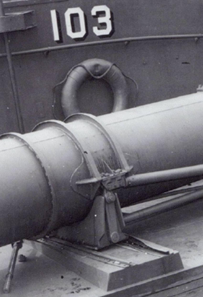
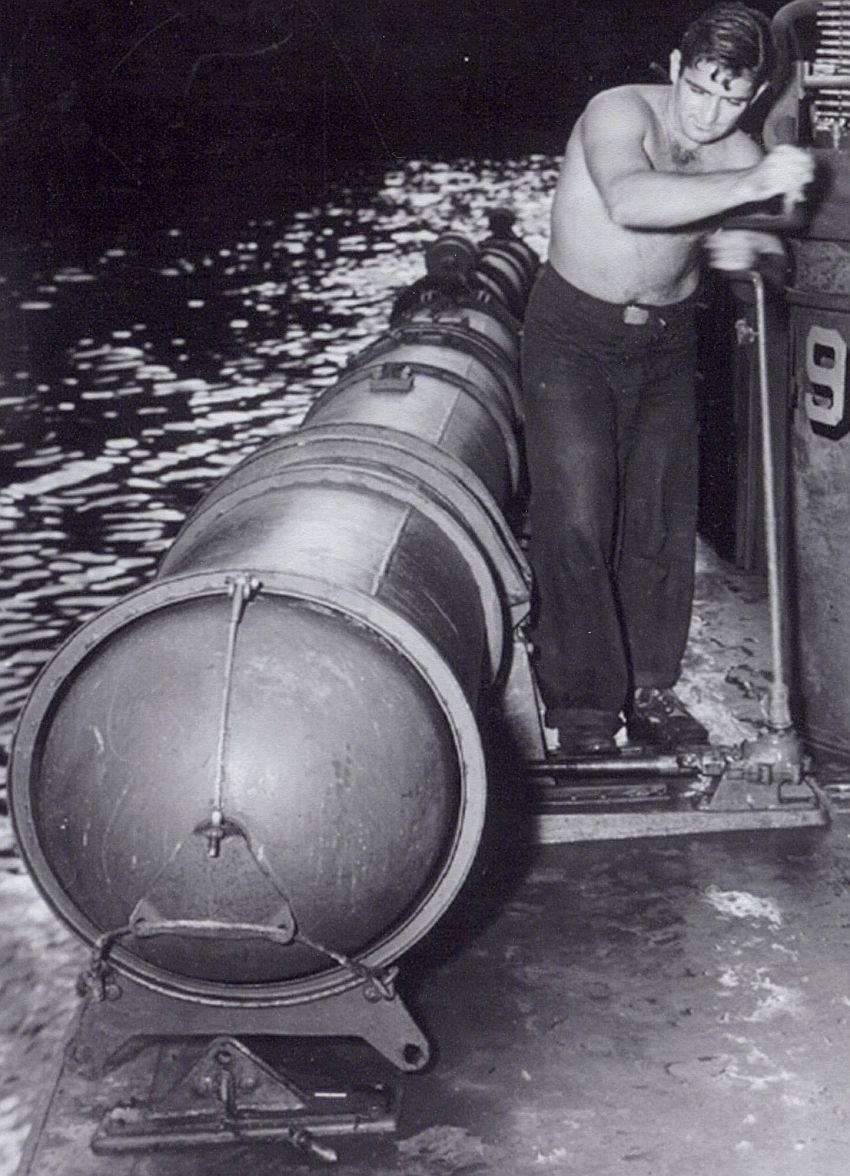
Does anyone have any detail photos or drawings on the torpedo tube guide portion where it tracks out. I'm stuck on how the hardware is mounted to the wood bases.
Thanks
Dave
David Waples |
Total Posts: 1679 | Joined:
Jan 2, 2007 - 9:55pm | IP
Logged
|
|
David Waples
TOP BOSS
|
Posted on: Dec 19, 2011 - 5:59am
|
I was actually able to answer my own question. I found in my huge pile of references detailed drawings for the torpedo tubes. Included is a detailed drawing of the guides which consists of a "z" bar affair bolted to a plate. The bolts are on the outside of the guides. I'll try and post some pictures later. I'm going to try and build this detail into my model.
Dave
David Waples |
Total Posts: 1679 | Joined:
Jan 2, 2007 - 9:55pm | IP
Logged
|
|
David Waples
TOP BOSS
|
Posted on: Dec 19, 2011 - 6:03am
|
I was actually able to answer my own question. I found in my huge pile of references detailed drawings for the torpedo tubes. Included is a detailed drawing of the guides which consists of a "z" bar affair bolted to a plate. The bolts are on the outside of the guides. I'll try and post some pictures later. I'm going to try and build this detail into my model.
Dave
David Waples |
Total Posts: 1679 | Joined:
Jan 2, 2007 - 9:55pm | IP
Logged
|
|
|
|
Jeff D
Moderator

|
 Posted on: Dec 19, 2011 - 6:25am Posted on: Dec 19, 2011 - 6:25am
|
You answered my question too. 
|
Total Posts: 2200 | Joined:
Dec 21, 2006 - 1:30am | IP
Logged
|
|
David Waples
TOP BOSS
|
Posted on: Dec 19, 2011 - 7:15pm
|
No need for me to add the drawings. Excellent reference photo! What I'm not picking up on in the photos is a plate under the z bars where the tube cradle slides. I'm wondering if these z bars, or guides, or rails, are only secured by the bolts directly into the wood platforms? Any thoughts?
Dave
David Waples |
Total Posts: 1679 | Joined:
Jan 2, 2007 - 9:55pm | IP
Logged
|
|
Jeff D
Moderator
|
Posted on: Dec 20, 2011 - 4:54am
|
Going by the photos and the carriage and plate drawing, it looks to me as if the 19 screws alone held each carriage guide and plate. The turntable at the aft end of the tube would take the brunt of the launching force.
|
Total Posts: 2200 | Joined:
Dec 21, 2006 - 1:30am | IP
Logged
|
|
TheBridge
TOP BOSS

|
Posted on: Dec 20, 2011 - 6:32am
|
I would agree with you Jeff on your analysis. The launch thrust is flat and if anything their might be some down-pressure on the forward mount as the weight of the torpedo, in its split second during launch, would rest on the front lip of the tube.
|
Total Posts: 318 | Joined:
Nov 22, 2009 - 3:04pm | IP
Logged
|
|
alross2
TOP BOSS
|
Posted on: Feb 12, 2012 - 1:54pm
|
After looking at the photos and drawings, I think I agree with Jeff - there had to have been a mechanical holddown of some sort. Here's my thoughts (remembering I have no engineering background... ) )
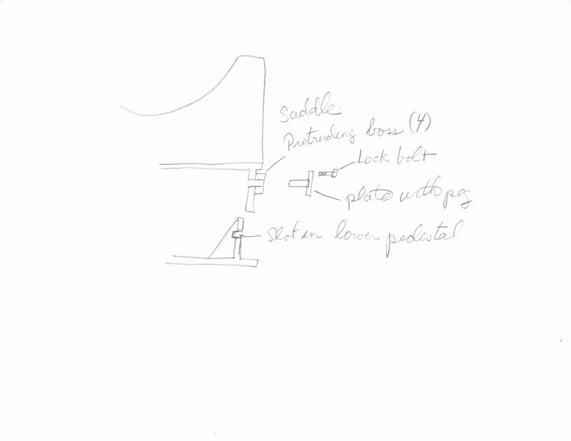
There are four slots in the turntable base vertical tube. The saddle tube fits down over the turntable base tube and has four bosses on it. Each boss has a large diameter hole and a small diameter hole. I didn't see any text about threads on the drawing, but would guess that a plate with a large diameter pin welded to it would be attached to the boss with a bolt through the smaller hole after the saddle tube was placed over the turntable tube. The pin would be long enough to pass through the slot, acting as a stop for vertical movement. The interior gussets in way of the slot may have had a corresponding slot milled in their edge where they met the tube, but that wouldn't be much of a problem. The elongated slots would allow the tube to pivot (only 12 degrees needed) and would act as a mechanical stop (pin hitting the end of the slot) to prevent an overzealous torpedoman from cranking the tube too far.
Plausible??
Al
|
Total Posts: 993 | Joined:
Oct 30, 2006 - 8:19pm | IP
Logged
|
|